background image

21

W415-0297 / 

Q

 / 

08.23.18

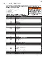
10.0 REPLACEMENTS

Contact your dealer or the factory for questions concerning prices and policies on replacement parts. Normally 
all parts can be ordered through your Authorized dealer / distributor. 

FOR WARRANTY REPLACEMENT PARTS, A PHOTOCOPY OF THE ORIGINAL INVOICE WILL BE 
REQUIRED TO HONOUR THE CLAIM.

When ordering replacement parts always give the following information:

Model & Serial Number of appliance

Installation date of appliance

Part 

number

Description of part

Finish

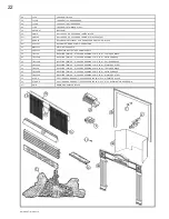
* IDENTIFIES ITEMS WHICH ARE NOT ILLUSTRATED. FOR
FURTHER INFORMATION, CONTACT YOUR AUTHORIZED DEALER.

41.1

FAILURE TO POSITION THE PARTS 

IN ACCORDANCE WITH THIS 

MANUAL OR FAILURE TO USE ONLY 

PARTS SPECIFICALLY APPROVED 

WITH THIS APPLIANCE MAY 

RESULT IN PROPERTY DAMAGE OR 

PERSONAL INJURY.

!

WARNING

COMPONENTS

REF

PART NO.

DESCRIPTION

1

W357-0001

PIEZO IGNITER

2

W662-0001

OXYGEN DEPLETION SENSOR SYSTEM  - NG

2

W662-0005

OXYGEN DEPLETION SENSOR SYSTEM - LP

3*

W680-0004

THERMOPILE

4

W725-0030

NATURAL GAS VALVE

4

W725-0031

PROPANE GAS VALVE

5*

W385-0334

NAPOLEON LOGO

6*

W750-0112

20FT OF WIRE

7

GL-664

ONE PIECE LOG SET (W135-0335)

8*

W361-0016

GLOWING EMBERS

9*

W550-0001

CHARCOAL EMBERS

10

W010-0764

PAN BURNER (NG)

10

W010-0987

PAN BURNER (LP)

11

W456-0039

#39 NATURAL GAS BURNER ORIFICE

11

W456-0053

#53 PROPANE GAS BURNER ORIFICE

12

W335-0050

HOOD

13

W565-0058

CURTAIN MESH

14

W555-0033

CURTAIN ROD

15*

W080-0742

CURTAIN ROD BRACKET

16

W500-0194

PLATE COVER

17

W630-0010

BLACK TASSELS

ACCESSORIES

REF

PART NO.

DESCRIPTION

18*

W660-0081

SWITCH, THERMOSTAT

19*

F40

ON/OFF REMOTE

19*

F50

THERMOSTATIC REMOTE

19*

F50DR

DESIGNER THERMOSTATIC REMOTE - RED

19*

F50DY

DESIGNER THERMOSTATIC REMOTE - GREY

19*

F50DK

DESIGNER THERMOSTATIC REMOTE - BLACK

20*

W660-0013

MODULATING REMOTE

21*

GD825N

MODULATING REGULATOR  NG

21*

GD825P

MODULATING REGULATOR  LP

22*

W660-0026

PROGRAMMABLE TIMER, BATTERY OPERATED

23

GZ550-1KT

BLOWER KIT

24*

W500-0033

VARIABLE SPEED SWITCH WALL MOUNTING PLATE

25*

111KT

OUTSIDE AIR KIT

26*

112KT

ADAPTOR PLATE FOR OUTSIDE AIR KIT

27

HOIK-3

ORNAMENTAL INSETS - BLACK

27

HOIG-3

ORNAMENTAL INSETS - GOLD

27

HOISS-3

ORNAMENTAL INSETS - SATIN CHROME

Summary of Contents for Grandville GVF36-2P

Page 1: ...EFERENCE NEVER LEAVE CHILDREN OR OTHER AT RISK INDIVIDUALS ALONE WITH THE APPLIANCE INSTALLATION AND OPERATING INSTRUCTIONS 1 23B Wolf Steel Ltd 24 Napoleon Rd Barrie ON L4M 0G8 Canada 103 Miller Driv...

Page 2: ...ETERMINING CONFINED OR UNCONFINED SPACE 7 3 3 GAS INSTALLATION 8 3 4 OPTIONAL WALL SWITCH THERMOSTAT 9 3 5 MOBILE HOME INSTALLATION 9 4 0 FRAMING 10 4 1 MINIMUM CLEARANCE TO COMBUSTIBLES 11 4 2 MINIMU...

Page 3: ...d hearth guards to protect children from hot surfaces These screens and guards must be fastened to the floor Any safety screen or guard removed for servicing must be replaced prior to operating the ap...

Page 4: ...7 CMR 30 00 upon the sale of the appliance from http www napoleonfireplaces com Webshare installation_manuals mass_requirements pdf WARNING CARBON MONOXIDE POISONING MAY LEAD TO DEATH EARLY SIGNS OF C...

Page 5: ...on for the appliance is in the center of a building thereby allowing the most efficient use of the heat created The location of windows doors and the traffic flow in the room where the appliance is to...

Page 6: ...TER COLUMN SIT CONTROL 820637 SIT CONTROL 820636 OPERATING PILOT OXYPROTECTOR 8214 OPERATING PILOT OXYPROTECTOR 8404 ABOVE 2 000FT CONSULT LOCAL AUTHORITY HAVING JURISDICTION NOT FOR USE WITH SOLID FU...

Page 7: ...phere have a continuous water vapour retarder with a rating of 1 perm 6 x 10 11 kg per pa sec m2 or less with openings gasketed or sealed and B Weather stripping has been added on openable windows and...

Page 8: ...3 EXAMPLE 2 If in this example a solid door separates Room 1 from Room 2 the volume of Room 2 could not be used In this case the maximum BTU h would be Maximum BTU h 800x1000 16 000 BTU h 50 This woul...

Page 9: ...HEN ATTACHING GAS SUPPLY PIPE TO PREVENT DAMAGING GAS LINE ALWAYS LIGHT THE PILOT WHETHER FOR THE FIRST TIME OR IF THE GAS SUPPLY HAS RUN OUT WITH THE GLASS DOOR OPENED OR REMOVED PURGING OF THE GAS S...

Page 10: ...C AND UL763 SHALL BE CONSIDERED NON COMBUSTIBLE MATERIALS MINIMUM CLEARANCE TO COMBUSTIBLES MUST BE MAINTAINED OR A SERIOUS FIRE HAZARD COULD RESULT THE APPLIANCE REQUIRES A MINIMUM ENCLOSURE HEIGHT M...

Page 11: ...may occur at or after a minimum distance of 2 away from the side of the appliance Thereafter the depth of any protrusions must be of equal to or less than the distance from the side of the appliance...

Page 12: ...sure space around and above the appliance must be left unobstructed 4 3 MINIMUM MANTEL CLEARANCES WARNING RISK OF FIRE MAINTAIN ALL SPECIFIED AIR SPACE CLEARANCES TO COMBUSTIBLES FAILURE TO COMPLY WIT...

Page 13: ...3 4 or a 1 finished wall thickness The nailing tabs must not be removed nailing tab WARNING RISK OF FIRE NEVER OBSTRUCT THE FRONT OPENING OF THE APPLIANCE THE FRONT OF THE APPLIANCE MUST BE FINISHED...

Page 14: ...lusive to Napoleon Fireplaces provide a unique and realistic glowing effect that is different in every installation Take the time to carefully position the glowing embers for a maximum glowing effect...

Page 15: ...to thin small irregular pieces as only the exposed edges of the fibre hairs will glow NOTE The ember material will only glow when exposed to direct flame however care should be taken to not block the...

Page 16: ...ERSAL HARNESS WHEN INSTALLED ENSURE THAT ANY EXCESS WIRE IS CONTAINED PREVENTING IT FROM MAKING CONTACT WITH MOVING OR HOT OBJECTS 51 5 Remove the backing of the logo supplied and place on the screen...

Page 17: ...e blower does not touch the appliance base or the firebox Attach the connectors from the black and white wires to the thermal switch and secure the thermal switch bracket to the bottom left of the uni...

Page 18: ...ront of the back log G Turn gas knob counter clockwise to pilot H Depress and hold gas knob while lighting the pilot with the push button ignitor Keep knob fully depressed for one minute then release...

Page 19: ...y allow 15 to 30 minutes for the final flame colour to be established AIR SHUTTER ADJUSTMENT MUST ONLY BE DONE BY A QUALIFIED INSTALLER AIR SHUTTER OPENING VENTURI BURNER ORIFICE 49 1 AIR SHUTTER OPEN...

Page 20: ...CAUTION Label all wires prior to disconnection when servicing controls Wiring errors can cause improper and dangerous operation Verify proper operation after servicing This appliance and its venting...

Page 21: ...HERMOPILE 4 W725 0030 NATURAL GAS VALVE 4 W725 0031 PROPANE GAS VALVE 5 W385 0334 NAPOLEON LOGO 6 W750 0112 20FT OF WIRE 7 GL 664 ONE PIECE LOG SET W135 0335 8 W361 0016 GLOWING EMBERS 9 W550 0001 CHA...

Page 22: ...NELS 35 TB336K BEVELLED TRIM KIT 3 COVERS OPENING 37 W X 33 H TEXTURED BLACK 35 TB336AB BEVELLED TRIM KIT 3 COVERS OPENING 37 W X 33 H ANTIQUE BRASS 35 TB336PB BEVELLED TRIM KIT 3 COVERS OPENING 37 W...

Page 23: ...low Service or replace Oxygen Depletion Sensor System Correct piping and or regulator to provide correct pressure Ensure adequate supply pressure Pilot goes out when the gas knob is released The gas v...

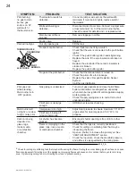
Page 24: ...and see if pilot flame flutters diminishes or extinguishes especially when main burner ignites Monitor appliance supply working pressure Check if supply piping size is to code Correct all undersized...

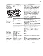
Page 25: ...of the methods described in ANSI Z223 1 NFPA 54 or the applicable local code Not enough ventilation air Increase fresh air supply Use one of the methods described in ANSI Z223 1 NFPA 54 or the applica...

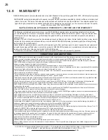
Page 26: ...r plated trim or other components due to water weather damage long periods of dampness condensation damaging chemicals or cleaners will not be the responsibility of NAPOLEON All parts replaced under t...

Page 27: ...27 W415 0297 Q 08 23 18 13 0 SERVICE HISTORY 43 1...

Page 28: ...28 W415 0297 Q 08 23 18 44 1 14 0 NOTES...

Reviews: