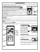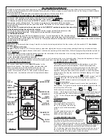
CANADIAN EQUIPMENT REQUIREMENTS:
This digital apparatus does not exceed the (Class A / Class B)
limits for radio noise emissions from digital apparatus set out in
the Radio Interference Regulations of the Canadian Department of
Communication. This device complies with RSS-210 of Industry
and Science Canada. Operation is subject to the following two
conditions: (1) this device may not cause interference, and (2) this
device must accept any interference, including interference that
may cause undesired operation of the device.
W415-0628 / G / 04.09.10
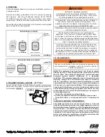
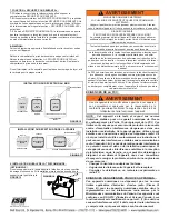
9. TRANSMITTER WALL MOUNT:
(OPTIONAL)
Secure the wall cradle to the desired wall location using screws,
and anchors if required. If wall mount is not desired wall cradle can
be discarded.
FIGURE 16
FIGURE 18
FCC REQUIREMENTS:
NOTE: This equipment has been tested and found to comply
with the limits for a Class B digital device, pursuant to Part 15 of
the FCC Rules. These limits are designed to provide reasonable
protection against harmful interference in a residential
installation. This equipment generates, uses and can radiate radio
frequency energy and, if not installed and used in accordance
with the instructions, may cause harmful interference to radio
communications. However, there is no guarantee that interference
will not occur in a particular installation. If this equipment does
cause harmful interference to radio or television reception, which
can be determined by turning the equipment off and on, the user
is encouraged to try to correct the interference by one or more of
the following measures:
- Reorient or relocate the receiving antenna.
- Increase the separation between the equipment and receiver.
- Consult the dealer or an experienced radio TV technician for
help.
!
WARNING
Changes or modifi cations to this unit not expressly approved by the
party responsible for compliance could void the user’s authority to
operate the equipment.
!
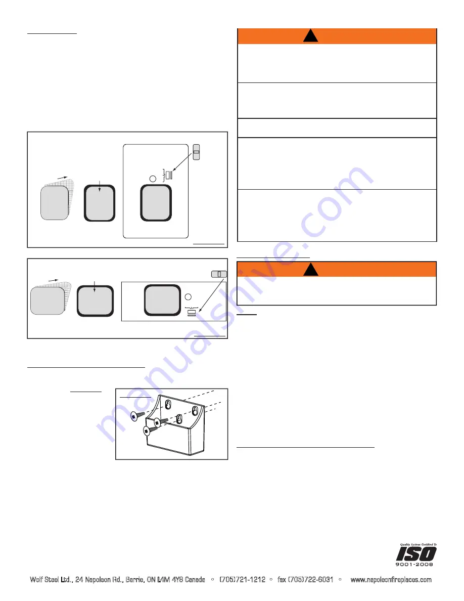
8. FINISHING:
Follow the diagram based on your receiver installation, wall mount
or fi replace mount.
Remove the battery compartment from the receiver by pressing
and releasing. Peel the self adhesive backing off the “PRESS
TO OPEN” sticker and affi x to the front surface of the battery
compartment. Replace the battery compartment into the receiver.
Secure the slide switch horizontally for the fi replace mounting plate
and vertically for the wall faceplate.
PRESS TO OPEN
AFFIX
BATTERY
COMPARTMENT
PEEL
STICKER
PRESS TO OPEN
PRESS TO OPEN
BAT.LOW
OFF REMOTE ON
FIREPLACE MOUNTING PLATE
SLIDE
SWITCH
RECEIVER FIREPLACE MOUNT
FIGURE 17
FIREPLACE REMOTE
ON
REMOTE
OFF
BAT.LOW
PRESS
TO OPEN
PEEL
PRESS
TO OPEN
AFFIX
BATTERY
COMPARTMENT
STICKER
PRESS
TO OPEN
WALL FACE PLATE
SLIDE
SWITCH
RECEIVER WALL MOUNT
FIGURE 18
Wolf Steel Ltd., 24 Napoleon Rd., Barrie, ON L4M 4Y8 Canada • (705)721-1212 • fax (705)722-6031 • www.napoleonfireplaces.com
ARNING
W
!
PROPERTY DAMAGE HAZARD.
EXCESSIVE HEAT CAN CAUSE PROPERTY DAMAGE.
The appliance can stay ignited for many hours. Take care to
turn off the appliance if it is unattended by an adult.
FIRE HAZARD. CAN CAUSE SEVERE INJURY OR DEATH.
The receiver causes the ignition of the appliance. The
appliance can turn on suddenly. Keep away from the burner,
especially when operating on the BACKUP switch.
Modifi cation of any part of this kit will void any warranty claims
and could create a fi re hazard.
The transmitter and the receiver are radio frequency
appliances. If the receiver is mounted inside metallic cases,
severe loss of performance (reduction of working range) may
result. When the receiver is installed inside the steel appliance
shell, it is recommended that the transmitter be located no more
than 10’ away for consistent operation.
In the event of prolonged absences, the F50 should not be
left in thermostat mode or used as a primary heat source. If
the transmitter batteries fail while the appliance is operating
the receiver will assume control and shut OFF the appliance
after twenty-four hours. If the transmitter batteries fail while the
appliance is not operating the appliance will remain OFF.


