


EN
W415-1789 / C / 01.29.19
15
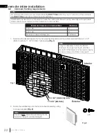
remote exterior installation
5.2 minimum framing requirements
See “minimum framing requirements” in exterior installation section for details.
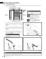
1. Determine the location for the 6” (152mm) collar plate assembly on the appliance enclosure, and then cut a
hole 6” (152mm) in diameter
(Fig. 1)
.
note:
Ensure to create the Ø 6” (152mm)
hole within the top 12” (30.5cm) of the
enclosure
(Fig. 1)
.
Top of Enclosure
12”
(30.5cm)
Air Outlet
Opening
Ø 6”
(152mm)
Fig. 1
Left Side Profile View
2. Using appropriate fasteners (not supplied), secure the 6” (152mm) collar plate assembly over the hole inside
the bulkhead
(Fig. 2)
.
3. Install 6” rigid steel venting (not supplied) from the appliance enclosure to the blower housing assembly
(Fig.
3)
.
Fig. 2
Fig. 3
GLASS GUARD
LVX 38 illustrated
Inside View
of Bulkhead
(Some Framing
and Finishing
Hidden for Clarity)
Interior
Exterior
Interior
Exterior
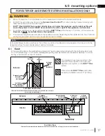
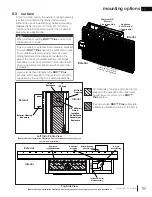
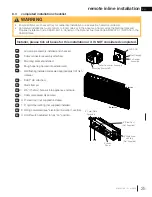
5.3 ducting installation
No materials of any type
permitted in this area with
the exception of an approved
appliance vent system or the
DHC™ Plus
system.
Recommended
DHC™ Plus
collar plate assembly installation
zone (12” [30.5cm]).


