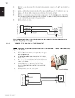
NOTE: Leave enough wire so that the appliance can be removed from the enclosure without
disconnecting the power supply.
A.
Remove the securing screw from the electrical cover plate, located on the right hand side of the
fi replace.
B.
Add an electrical box connector and feed the supply wires through the 7/8" (22mm) knock out.
C.
Separate the black, white and green wires that have the marrets on them.
D.
Remove the marrets and secure the black wire (power L1) to the black (power L1) lead of the
power supply. Connect the white wire from the unit to the white (neutral) wire from the power
supply. Connect the green wire to the ground wire.
E.
Resecure the cover plate.
BLACK
WHITE
BLACK
WHITE
4
6
1
1
-
:
1
0
8
&
3
+
6
/
$
5
*
0
/
'
*
3
&
1
-
"
$
&
GREEN
GREEN
(L1)
(N)
(G)
MARRET
+
6
/
$
5
*
0
/
'
*
3
&
1
-
"
$
&
MARRET
RED
RED
RED
RED
GREEN
GREEN
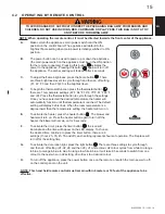
THERMOSTAT
A.
Remove the electrical box cover plate from the right
side of the fi replace.
B.
Feed the thermostat wires through the 7/8" (22mm)
knock out.
C.
Pull out the two red wires from the electrical box and
remove the marret.
D.
Connect two wires to the newly exposed wires
and run to the thermostat location. Connect to the
thermostat.
E.
Replace and rescure the cover plate.
NOTE: Thermostat (not supplied) must be rated for 120 vac minimum 15 amps. This function only
operates the heater.
3.3.3
CONNECTING A WALL THERMOSTAT
EN
W415-1299 / D /
12.03.14
12


