


4.2.5 Set the volume
Set the VOLUME to get proper volume without feedback.
4.2.6 Change the frequency
If you need to change the receiver frequency, press the key
“
SET
”
, then the
“
MHz
”
will flash, it
means you can change the frequency now, to change receive frequency, press the UP key (
▲
) or the
DOWN key (
▼
), then the frequency and the channel will augment or abate synchronously.
4.2.7 Locked and Unlocked
The buttons of true diversity receiver 8122 could be locked. To lock the buttons, press the UP key
(
▲
) and keep for 5 seconds, the
“
LoC on
”
will appear in the LCD screen, and the buttons will be
disabled, after this, if you press the buttons, the
“
LoC
”
will appear on the LCD screen, means the
buttons was locked. To unlock the buttons, press the UP key (
▲
) and keep for 5 seconds, the
“
LoC
oFF
”
will appear on the LCD screen, means the buttons was unlocked.
4.2.8 Automatically Scan
Receiver 8122 can scan the signal frequency of the microphone and store it automatically. Please
do as following: first make sure the microphone was turned on, then press the DOWN key (
▼
) until
“
SCAN
”
appears in the screen, release the key, press UP key (
▲
) or DOWN key (
▼
) to scan signal
upwards or downwards. W hen it scan the signal, it will stop scanning automatically and storage the
date. You can also press
“
SET
”
key to stop scanning. Please pay attention: before scanning, make sure
there is only one microphone on working, and there is no interferential signal around it, otherwise it will
stop scanning by error signal.
4.2.9Adjust squelch
We can adjust the squelch gate to get a different receiver distance on Receiver 8122, The way is:
Press
“
SET
”
key and don
’
t release it until it appears
”
SqL-90
”
, Press UP key (
▲
), the data on the
screen will enlarge to -85,-80 etc., it means the squelch gate are increased, accordingly, the receive
distance shorten and the anti-jamming performance improving; Press DOWN key (
▼
), the data on the
screen will diminish to -95 and etc., it means the squelch gate are declined, accordingly, the receive
distance will enlarge and the anti-jamming performance reduce. After this, press
“
SET
”
key to confirm
and exit.
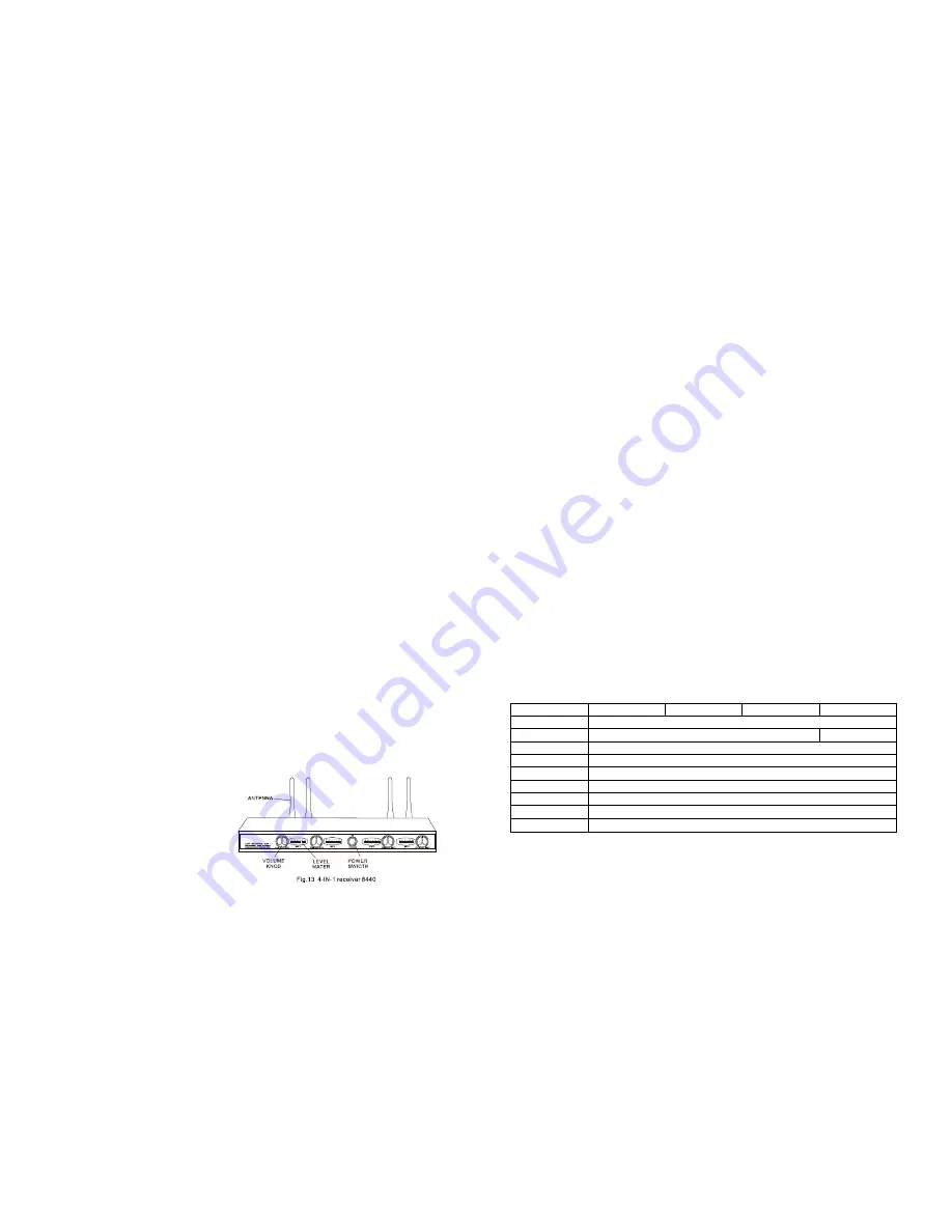
4.3 Receiver 8440
4.3.1 Install and Place receiver
Receiver 8440 was shown in Fig.13.
There are four receive units in the receiver.
Take out the receiver and the receive
antennas from packing box, revolve the four
~7~
antennae to the four ANT sockets on the rear panel of the receiver, place the receiver near the
performance area. Point the antennae upward. Make sure that the transmitter (microphone) will never
get any closer to the receiver than 10 ft (3m), optimum separation is 16 ft (5m). There should always be
a direct line of sight between the microphone and receiver. Place the receiver least 5 ft (1.5m) away
from any big metal objects, walls, scaffolding, ceilings, etc.
4.3.2 Switch on the power
Check if the AC voltage stated on the rear panel of the receiver matches the AC electric socket in
the wall before connecting the power cable in Receiver. Otherwise may cause irreparable damage to
the unit.
4.3.3 Connect the signal cable
Connect MAXED OUTPUT in receiver and MIC INPUT in the amplifier with the supplied
unbalanced audio cable. If necessary, you can use other audio cables, and connect 4 output sockets
(MIC1~MIC4) to amplifier respectively.
4.3.4 Adjust volume
Adjust the volume of the receiver and amplifier to
“
MIN
”
and turn on the receiver, the power supply
indicator will light on, and receiver can work now. Turn on the microphone and speak with it, the LED
level meter will denoting the magnitude of the sound. Then adjust the volume of the receiver and the
amplifier to get the best volume. Please pay attention: don
’
t adjust the volume too big to avoid
feedback, otherwise it may cause irreparable damage to your sound box.
5 Specifications
5.1 Specifications of microphones
Model
T11
T12
T14
T16
Freq Range
730~950MHz
Freq number
96
1
Freq stability
±
10ppm
Modulation
FM
RF output
10~50mW
Audio bandwidth
40~18000Hz
T.H.D. at 1kHz
≤
0.5%
Power supply
2
×
1.5V
Battery left
15 hours
~8~


