6
StarLink
™
SLE Series Alarm Communicators -- Installation Instructions
pulse format is selected and the
Sum-Check
box is
checked, be sure to install jumper #2 in jumper block la-
beled "X5".
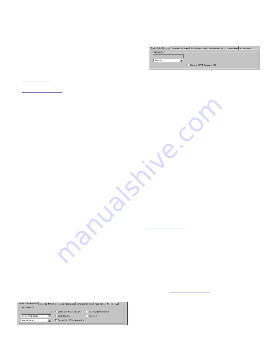
A "Point ID" (also called "Contact ID") receiver format pro-
gramming example:
The panel can transmit to any standard central-station
receiver; confirm with the central station the options and
type of receiver for each telephone number used.
Note:
A receiver reporting format must be entered for
each telephone number used, but each telephone number
may be assigned a different format.
Supported alarm reporting formats include:
Contact ID
Ademco Slow
Radionics Fast
Silent Knight Fast
Radionics Slow
Universal High Speed
CAUTION:
The installer should always be certain an
area code is programmed into the control panel.
Optional:
If you wish the StarLink radio to report a code
and zone number (Contact ID by default) to the central sta-
tion in response to a triggered input event, see the table
"
STARLINK RADIO RELATED EVENT REPORT
CODES
" (located on the previous page) that includes the
most common Contact ID and Pulse 4/2 alarm codes.
Note:
These event codes and zone numbers can be
changed from the Management Center screen (located at
www.napconoc.com
).
Upon alarm, the NOC optionally sends an SMS message to
a third party that includes the appropriate Contact ID alarm
code, including the zone or user number, if applicable.
Programming StarLink Radio Troubles
The StarLink radio can detect multiple troubles as indicated
by the "Red Trouble LED" (labeled "
D5
"). For these trou-
bles to be annunciated, there are several methods, some of
which are configurable at the Management Center screen
(located at
www.napconoc.com
), as follows:
Method 1:
Dedicate a panel zone to activate a trou-
ble sounder when an open is detected. With Napco
control panels, program a dedicated zone for Day Zone,
Mini-sounder on Alarm and No Bell on Alarm. Wire the
zone as indicated in the wiring diagrams further in this
manual.
65mA during standby,
and almost 400mA during trans-
missions
(for less than 1 second). (
Note:
80mA with
peak RF transmission current of 400mA for model SLe-
GSM-8D-3/4G and SLE-CDMA-8D).
Attach antenna before applying power !
STEP 5: SIGNAL VERIFICATION
After triggering channels, use the StarLink radio Signal
Verification to ensure that the StarLink radio Network has
properly received the signals.
Verify Online
: To verify that the signals have been
received by the StarLink radio Network online, go to
www.napconoc.com
, log in with your Username and
Password, type the StarLink radio
ID#
(printed on the
label affixed to the radio circuit board inside the hous-
ing), then press the keyboard
Enter
key.
IMPORTANT
: Verify that the signals transmitted by the
StarLink radio have been properly received by your central
station before leaving the premises.
NOTE:
This equipment has been tested and found to
comply with the limits for a Class B Unintentional Radiator,
pursuant to Part 15 of the FCC Rules. These limits are
designed to provide reasonable protection against harmful
interference in a residential installation. This equipment
generates, uses, and can radiate radio frequency energy
and, if not installed and used in accordance with the In-
struction Manual, may cause harmful interference to radio
communications. However, there is no guarantee that in-
terference will not occur in a particular installation. If this
equipment does cause harmful interference to radio or tele-
vision reception, which can be determined by turning the
equipment off and on, the user is encouraged to try to cor-
rect the interference by one of more of the following
measures: 1. Reorient or relocate the receiving antenna;
2. Increase the separation between the equipment and re-
ceiver; 3. Connect the equipment into an outlet on a circuit
different from that to which the receiver is connected; 4.
Consult the dealer or an experienced radio/TV technician
for help.
CONTROL PANEL PROGRAMMING
To program the central station receiver reporting format,
use PCD-Windows Quickloader download software. Open
the
Digital Communications
screen,
Central Station Re-
ceivers
tab, as shown in the following images:
A "4/2" receiver format programming example:
If control panel reports using "4/2 with checksum", i.e., a


