If you set
3240
h
:07
h
to the value "1", three differential inputs are available
instead of six single-ended inputs.
NOTICE
•
EMC: For a DC power supply line longer than 30 m or when using
the motor on a DC bus, additional interference-suppression and
protection measures are necessary.
•
An EMI filter is to be inserted in the DC supply line as close as
possible to the controller/motor.
•
Long data or supply lines are to be routed through ferrites.
Commissioning
The Plug & Drive Studio software offers you an option for performing the
configuration and adapting the motor parameters to your application. You can
find further information in document Plug & Drive Studio: Quick Start Guide at
Observe the following notes:
CAUTION!
!
Moving parts can cause hand injuries.
If you touch moving parts during running operation, hand
injuries may result.
►
Do not reach for moving parts during operation. After
switching off, wait until all movements have ended.
CAUTION!
!
In free-standing operation, motor movements are
uncontrolled and can cause injuries.
If the motor is unsecured, it can, e.
g., fall down. Foot injuries or
damage to the motor could occur.
►
If you operate the motor free-standing, observe the motor,
switch it off immediately in the event of danger and make
certain that the motor cannot fall down.
CAUTION!
!
Moving parts can catch hair and loose clothing.
During running operation, moving parts can catch hair or loose
clothing, which may lead to injuries.
►
If you have long hair, wear a hairnet or take other suitable
protective measures when near moving parts. Do not work with
loose clothing or ties near moving parts.
CAUTION!
!
Risk of overheating or fire if there is insufficient cooling!
If cooling is insufficient or if the ambient temperature is too
high, there is a risk of overheating or fire.
►
During use, make certain that the cooling and environmental
conditions are ensured.
NOTICE
EMC: Current-carrying cables – particularly around supply
cables – produce electromagnetic alternating fields. These
can interfere with the motor and other devices.
Suitable measures may be:
►
Use shielded cables and earth the cable shielding on both
ends over a short distance.
►
Keep power supply cables as short as possible.
►
Use cables with cores in twisted pairs.
►
Earth motor housing with large contact area over a short
distance.
►
Lay supply and control cables separately.
Configuration via EtherCAT
Software connection
TIP
The following description assumes that an EtherCAT master from
Beckhoff with the TwinCAT software is used.
1.
Connect the EtherCAT master to the controller, see .
2.
Supply the controller with voltage.
3.
Obtain the ESI file that corresponds exactly to the used
firmware version
from the following sources:
a.
From the Nanotec website
the firmware and the ESI file can be found in the Plug & Drive Studio
download folder.
b.
From Nanotec support.
4.
Close the TwinCAT system manager if it is open.
5.
Then copy the ESI file to the TwinCAT subfolder:
■
If you use TwinCAT version 2, use folder
<TWINCAT INSTALL DIR>/
Io/EtherCAT
■
If you use TwinCAT version 3, use folder
<TWINCAT INSTALL
DIR>/3.1/Config/Io/EtherCAT
Example
Example: If TwinCAT 2 is installed on your computer under
path
C:\TwinCAT\
, copy the ESI file to path
C:\TwinCAT\Io
\EtherCAT\
.
6.
Open the ESI file with an editor. Find the AddInfo parameter. Enter:
■
the value "2" if you would like to integrate the controller as Box (factory
settings)
■
the value "0" if you would like to integrate the controller as NC-Axis
Save and close the file.
7.
Now restart the TwinCAT system manager. The ESI files are read in again
following a restart.
NOTICE
The cycle time of the sync signal must always be set to 1 ms. You
can set the bus cycle time (and, consequently, the interpolation time
in
60C2
h
) to integer multiples of 1 ms.
Test run
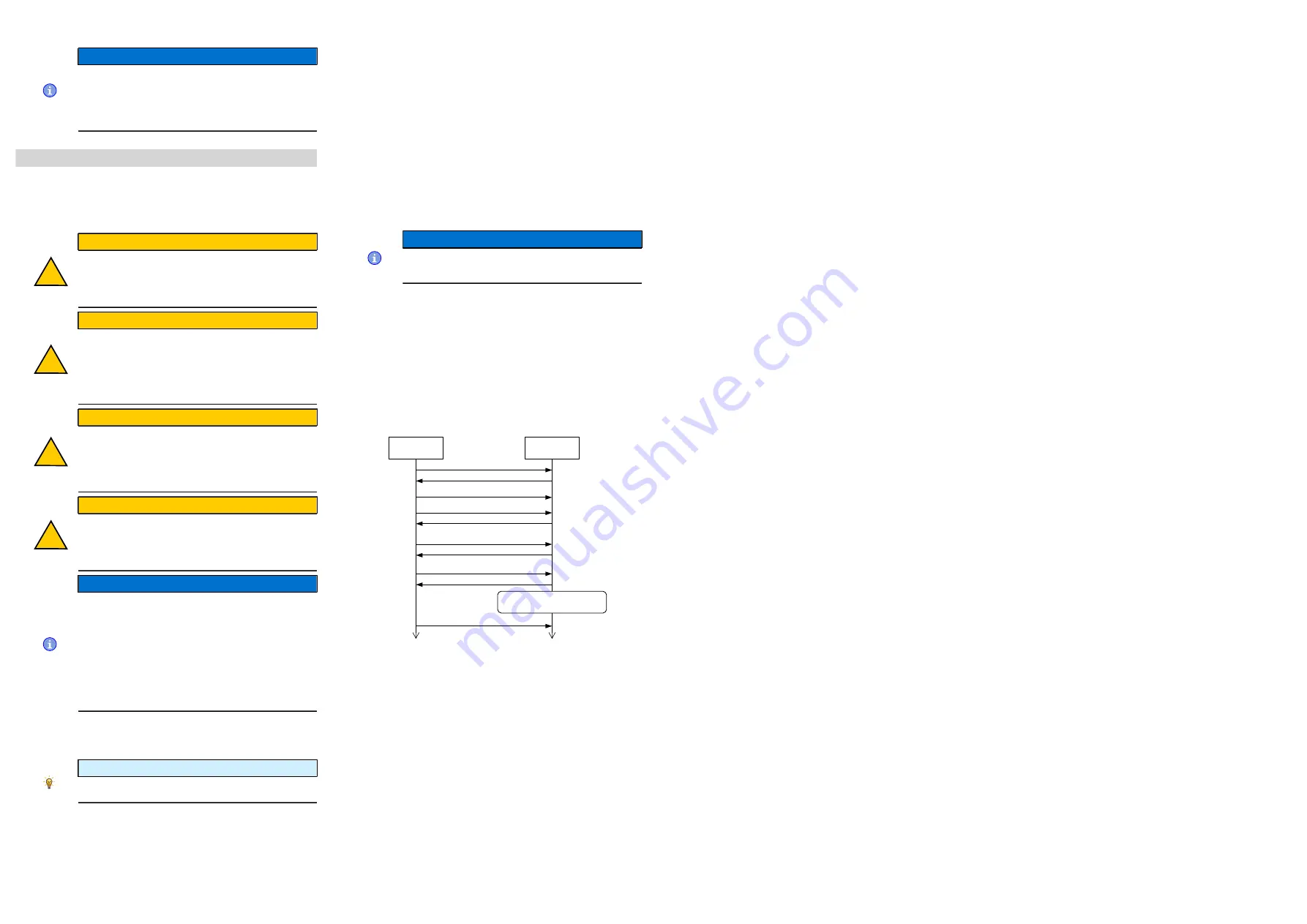
After configuring and the auto setup, a test run can be performed. As an
example, the
Velocity
operating mode is used.
The values are transferred from your EtherCAT master to the controller. After
every transfer, the master should use the status objects of the controller to
ensure successful parameterization.
1.
Select the Velocity mode by setting object
6060
h
(Modes Of Operation) to
the value "2".
2.
Write the desired speed in
6042
h
.
3.
Switch the power state machine to the Operation enabled.
The following sequence starts Velocity mode; the motor turns at 200 rpm.
Master
Controller
write 606
0
h
:00
h
= 02
h
read 606
1
h
:00
h
(= 02
h
?)
write 604
0
h
:00
h
= 0006
h
read 604
1
h
:00
h
(Bit 9, 5 und 0 = 1?)
write 6040
h
:00
h
= 0007
h
read 6041
h
:00
h
(Bit 9, 5, 4, 1, 0 = 1?)
write 6040
h
:00
h
= 000F
h
read 6041
h
:00
h
(Bit 9, 5, 4, 2, 1, 0 = 1?)
The controller is now running
in „Velocity“ mode.
read 6040
h
:00
h
= 0006
h
write 6042
h
:00
h
= 00C8
h
4.
To stop the motor, set controlword (
6040
h
) to "6".


