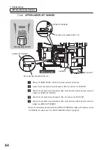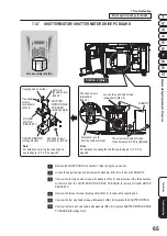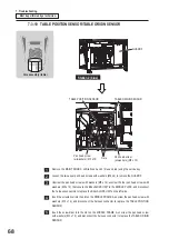
67
Test Mode
7. Troubleshooting
Troubleshooting
Disassembling/Replacement Procedure
- Must be performed by a technician -
7-3-9 TABLE DRIVE MOTOR
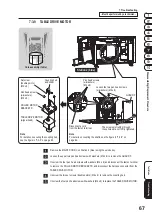
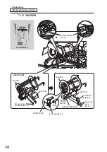
Core assembly (table)
Loosen the two pan head screws
(w/washers) (M4 x 6).
The screws protruding through
these holes are not firmly tightened.
GUARD F
Pan head screws
(w/washers)
(M4 x 6)
Disconnect a cord
from the faston terminal.
ROLLER MOTOR
BRACKET D
TABLE DRIVE MOTOR
(w/gearhead)
Set screw
(double points)
(M4 x 6)
Coupling hub
and slider
Pan head screws
(w/washers)
(M4 x 8)
Station 2 (blue)
Remove the MAINT DOOR C on Station 2 (blue) using the service key.
Loosen the upper two pan head screws with washers (M4 x 6) to remove the GUARD F.
Unscrew the four pan head screws with washers (M4 x 6) and disconnect the faston terminal
to remove the ROLLER MOTOR BRACKET D, and disconnect the harness connector from the
TABLE DRIVE MOTOR.
Unscrew the two set screws (double points) (M4 x 6) to remove the coupling hub.
Unscrew the four pan head screws with washers (M4 x 8) to replace the TABLE DRIVE MOTOR.
Note
For details on securing the coupling hub,
see the figure in “7-3-5” on page 62.
Note
For details on coupling the shafts, see the figure in “7-3-5” on
Summary of Contents for PAC-MAN SWIRL
Page 84: ...9 Parts List 84 27 29 28 18 19 25 26 24 21 23 22 28 31 20 30...
Page 88: ...9 Parts List 88 39 31 40 29 25 26 22 27 34 23 35 24 21 28 37 20 30 38 32 36 33 40...
Page 96: ...9 Parts List 96 9 5 Core Assembly 8 7 6 7 5 3 2 9 10 14 11 13 15 14 12 4 1 6 8...
Page 112: ...112...
Page 122: ......
Page 123: ......
Page 124: ......
Page 125: ......


