62
7. Troubleshooting
- Must be performed by a technician -
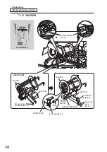
7-3-5 LIFTING MOTOR/ LIFTING MOTOR DRIVE PC BOARD
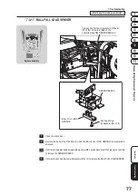
Core assembly (ball lift)
Pan head screw
(M4 x 6)
Coupling hub
Set screw (M4 x 6)
LIFT BRACKET B
Coupling hub and slider
LIFTING MOTOR
Pan head screw (M5 x 12)
Station 4 (green)
Pan head screw
(M3 x 6)
LIFTING MOTOR
DRIVE PC BOARD
(w/red mark)
Coupling hub
Coupling the shafts
Coupling slider
Lifting motor
shaft
No clearance
gaps
No clearance
gaps
Coupling hub
Lifting motor shaft
Note
When securing the coupling hub,
make sure that the motor shaft end
aligns with the lower end of the
coupling hub as in the figure.
Summary of Contents for PAC-MAN SWIRL
Page 84: ...9 Parts List 84 27 29 28 18 19 25 26 24 21 23 22 28 31 20 30...
Page 88: ...9 Parts List 88 39 31 40 29 25 26 22 27 34 23 35 24 21 28 37 20 30 38 32 36 33 40...
Page 96: ...9 Parts List 96 9 5 Core Assembly 8 7 6 7 5 3 2 9 10 14 11 13 15 14 12 4 1 6 8...
Page 112: ...112...
Page 122: ......
Page 123: ......
Page 124: ......
Page 125: ......


