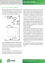
Power supply connection to the
communicator REGGAE GT
Connect power supply 10 – 15 V to the communicator
REGGAE GT Conduction of the supply voltage wires,
which is used for the communicator, must be secured
against possible circuiting sabotage Therefore it is
inappropriate to use the same power supply as for the
sensors, where the short circuit, in this usually relatively
easily accessible charge, causes communicator disfunc-
tion It is necessary that on the terminal plates of the
communicator, parameters listed in the description of
powering the communicator REGGAE GT are respected
Detailed information of power supply technical para-
meters can be found in the description of powering the
communicator REGGAE GT
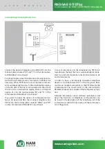
Power supply connection to the communicator
REGGAE GTbz/GTbzxxx
Connect power supply 230 VAC of the communicator RE-
GGAE GTbz/GTbzxxx to the terminal plates “PE”, “N” and
“L” on the power source circuit board Communicator
must always be connected to the protective conduc-
tor of the grid 230 V Carry out connection to the grid
230 V by using a flexble supply line with plug or by fi-
xed supply Flexible supply lines must lead through
bushing In the bushing this must be well fixed against
pulling out Bushing also protects the supply line again-
st abrasion of the insulation by sharp edges of the case
The network plug of the flexible supply line serves as
a means for disconnecting the communicator from
the grid The power socket must then be close to the
device and must be easily accessible Overcurrent
protection must be part of the installation of the soc-
ket If necessary, the flexible supply line with plug can be
replaced by wired connection Wired connection must
only be performed by a person with a valid certificate
for such activity! When connecting the wired connec-
tion, there must be an appropriate disconnecting me-
dium implemented as part of the electrical installati-
on in the building The nominal value of superposed
overcurrent protective element can be maximum 16
A Detailed information about technical parameters of
supply voltage can be found in the description of the po-
wer supply of the communicator REGGAE GTbz/GTbzxxx
Configuration and testing the
communicator
Configure the communicator locally on PC by using pro-
gramme NAM manager (connection via serial port), or
remotely again by using programme NAM manager The
process of configuration is listed in the user manual of
the programme NAM manager
Test all of the installed communication channels (co-
mmunication with AS/FAS, communication with ARC
and GSM/GPRS) Then also test functions of all installed
inputs and outputs For testing preferably use a serial
port connection to PC and programme NAM manager
Detailed information about testing options are listed in
the user manual of the programme NAM manager (in the
description of diagnostics of the communicator) For cur-
sory communicator function testing, status indication via
LED LD1 to LD4 can be used (see communicator status
indication via LED)
U
S
E
R
M
A
N
U
A
L
REGGAE GT/GTbz
Communicator for GSM (GPRS/SMS) transmission
www.namsystem.com
16

