EN
WWW.NAKAYAMATOOLS.COM
1
Main Description
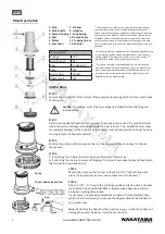
1. Wire
2. Wire Buckle
3. Pump Housing
4. Seal
5. Motor
6. Seal Cover
7. Oil Seal
8. Impeller
9. Snap Spring
10. Pump Cover
11. Tapping Screw
12. Strainer
Technical Data
Voltage:
12V
Load Current:
3A
Flow:
1100GPH/H
Head:
4M
Outlet Diam.:
29MM
Cable Length:
1M
* The manufacturer reserves the right to make minor changes
to product design and technical specifications without prior
notice unless these changes significantly affect the performance
and safety of the products. The parts described / illustrated in
the pages of the manual that you hold in your hands may also
concern other models of the manufacturer’s product line with
similar features and may not be included in the product you just
acquired.
* Please note that our equipment has not been designed for use
in commercial, trade or industrial applications. Our warranty
will be voided if the machine is used in commercial, trade or
industrial businesses or for equivalent purposes.
* To ensure the safety and reliability of the product and the
warranty validity, all repair, inspection, repair or replacement
work, including maintenance and special adjustments, must
only be carried out by technicians of the authorized service
department of the manufacturer.
Instructions
STEP 1
Remove the strainer from the bottom of the pump by depressing the lock tabs on both sides
of the pump.
Caution:
The strainer must always be properly installed before attaching and
running pump.
STEP 2
Determine the desired location for the pump. If only one pump is used it is usually located
where the water is deepest in the bilge while the boat is at rest. The installation must allow
for complete drainage of the hose. All water pockets must be eliminated by having the hose
running level or continuously upward.
STEP 3
Position the strainer so that pump nozzle is in the proper position to connect to the dis
-
charge hose.
STEP 4
A. If attaching the strainer to wood, fasten with stainless steel screws.
B. If attaching the strainer to metal or fibreglass, first mount a wooden block and then fasten
the strainer to the wooden block.
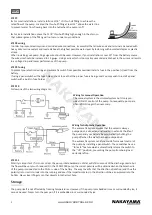
Pump
To exit above water line
Switch
Adaptor
Screw
Pump Base
STEP 5
Mount the pump on the strainer so that both 11/2” lock tabs snap into
place. (The pump may be reversed on these tabs if so desired. )
STEP 6
Attach 1 1/8” I. D . Hose to the discharge nozzle and fasten with a stainless
steel clamp. The hose (Model #80) is recommended because it will not
kink when making sharp bends.
If your pump is replacing a competitive model with small diameter hose
which is hard to replace, you may use the Adaptor Model #69 to adapt to
the smaller hose.
Note:
Restricting the flow from the pump by using a smaller hose does not
damage the pump. However, it will reduce the flow.
Summary of Contents for NP1160
Page 1: ...en gr WWW NAKAYAMATOOLS COM ART NO NP1160 024729...
Page 5: ...GR WWW NAKAYAMATOOLS COM 4 BHMA 7 A 11 8 I D 31cm 11 8 8 16 20 14 9 10 ON OFF OFF...
Page 6: ...GR WWW NAKAYAMATOOLS COM 5 BHMA 11 POS...
Page 7: ...DISPOSE OF PACKAGING RESPONSIBLY DO NOT DISPOSE OF ELECTRICAL GOODS IN HOUSEHOLD WASTE...


