


15
WWW
.N
AKAYAMA
T
OOLS
.
COM
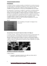
Picture 6
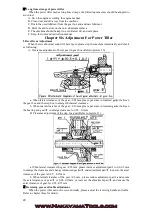
a. Loosen the locking bolts on the screw
b. Whirl the screw clockwise until it exposes a shortest length from the armrest.
c. Get the cable head into the clutch cable seat at the back of the gear-box assembly. Ensure the
cable head goes into the big hole on the cable seat.
d. Get the steel wire in the clutch cable into the M8 hole on the clutch fork arm seat, press the
clutch fork arm properly, and put the cable head into the cable seat.
e. Whirl the screw, loosen the clutch handle until the spring force in the clutch can reset the handle,
and then tighten the locknut.
f. Revering Cable Adjustment
g. Loosen the locking bolts on the screw
h. Whirl the screw clockwise until it exposes a shortest length from the armrest
i. Get the cable head into the reversing cable fork shaft at the side of the gear-box assembly. Ensure
the cable head goes into the big hole on the fork shaft
j. Properly pull the reversing fork shaft counterclockwise, get the cable into the gap the reversing
cable seat at the side of the gear box, and ensure the cable head goes into the big hole on the cable
seat.
k. Whirl the screw, loosen the reversing handle until the spring force in the clutch can reset the
handle, and then tighten the locknut
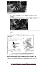
Picture 7
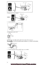
Adjustment of the Accelerator Cable
a. Turn down the accelerator switch clockwise.
b. Get the steel wire in the accelerator cable into the threading base and firm base on top of the
accelerator adjustment board of the engine.
c. Tighten the accelerator cable steel wire, and fasten the bolts on the retaining seat.
d. Adjust the accelerator switch repeatedly until the accelerator can be adjusted to the maximum
and minimum position.
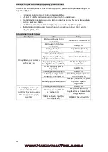
Ⅲ
Checking and Refueling
A.
Checking whether all the connection bolts are tightly fastened or not, and fasten the
connection bolts according to the torque listed in table 3(refer to the instruction manual for
engine for the screwing torque of bolt and nut respectively)
Summary of Contents for MB7000
Page 1: ...MB7000 Owner s manual WWW NAKAYAMATOOLS COM...
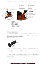
Page 3: ...3 WWW NAKAYAMATOOLS COM 1 2 3 4 5 6 7 8 1 2 3...
Page 4: ...4 WWW NAKAYAMATOOLS COM 1 8 55 8 2 16 140 1 7 1...
Page 5: ...5 WWW NAKAYAMATOOLS COM 1 2 2 1 2 3 80 90...
Page 6: ...6 WWW NAKAYAMATOOLS COM 4 SAE20 50 SAE 30 1 1750ml 20 50 1...
Page 7: ...7 WWW NAKAYAMATOOLS COM 2 2 3 3 1 1 2 2 3 4 5 6 1 2 25cm 25 40cm...
Page 8: ...8 WWW NAKAYAMATOOLS COM 3 4 10km h 5km h 1 2 3 4 5 6 7 8 1 5 3 5 4...
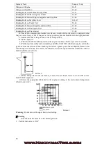
Page 9: ...9 WWW NAKAYAMATOOLS COM 1 2 150 3 800 4 1500 2000 8 20 3 150 1000 2 2000 0 0 0 0 0 0 0 0 0 0 0...
Page 10: ...10 WWW NAKAYAMATOOLS COM 1 2 3 4 5...
Page 11: ...11 WWW NAKAYAMATOOLS COM ring o ring...
Page 24: ...26 WWW NAKAYAMATOOLS COM...


