

①
When mounting a Spindle, refer to the Clamping
Area etched on the Spindle (Fig. 7).
CLAMPING AREA
(Clamping Area)
(33.6)
Fig. 7
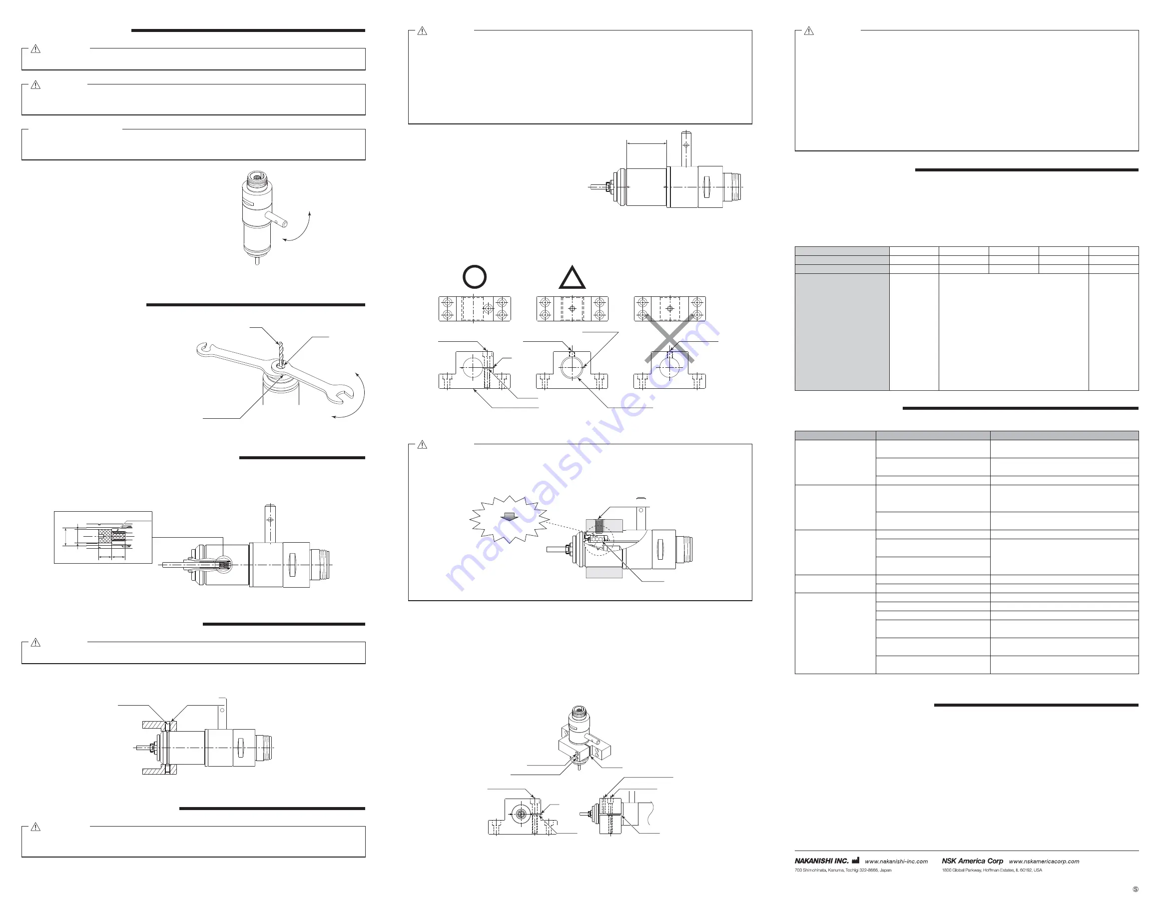
②
When installing a Spindle to the holder, recommended installation method is shown Fig. 8. Refer to "
③
How to
fabricate the Split Type Holder ". If this is not possible, install as shown in Fig. 9.
Fastening Bolt
Fastening Bolt
Fastening Bolt
Bushing Split
Spacer
Split Type Holder
Bushing with Slit
Slit
Fig. 8
Fig. 10
Fig. 9
Do not allow set screws to come directly in contact with the Spindle body as shown in Fig. 10, as this
will result in damage to the Spindle housing and internal components.
When installing, never clamp directly over the bearings, as this will result in bearing damage
(Refer to Fig. 11).
CAUTION
Fastening Bolt
Deformation
Bearing
Damage of Internal
Components
Fig. 11
③
How to fabricate the Split Type Holder
(1) Rough bore the inside diameter of the Split Type Holder.
(2) Cut a slit (Ex. Slit 2mm) wide.
(3) Tighten the Screw for Removal and Force Open the Slit Area.
(4) Insert a spacer (Ex. thickness = 2mm) into the Slit Area.
(5) Loosen the Screw for Removal, and tighten the fastening bolt with its speci
¿
ed torque.
(6) Finish the Split Type Holder so that the inside diameter of the Split Type Holder is
ȭ
26.8 with its
tolerance range from - 0.01mm to - 0.015mm, and its roundness and cylindricity of less than 5
ȝ
m.
(7) When inserting the Spindle loosen the Fastening Bolt, and tighten the Screw for Removal, widening
the Slit Area.
Front View
Side View
Fastening Bolt
Fastening Bolt
Screw for Removal
Screw for Removal
Slit
Spacer
Spacer
Spacer
Fastening Bolt
Fig. 12
・
How to con
¿
rm the correct tightening or clamping of the Spindles in the holder
Measure the current value of the CONTROLLER's power cord by the clamp meter.
Fasten the holder so that the increase in the no-load current value (during rotation at the maximum
rotation speed) with the Spindle fastened is 20mA (for type 120V) / 10mA (for type 200V / 230V)
or less, compared to the no-load current value (during rotation at the maximum rotation speed)
without fastening the Spindle. Do not over-tighten the Fastening Bolt. It may damage Spindle's
precision and shorten the life of the bearings.
・
The
¿
nal responsibility for ensuring holder
ʼ
s safety for use in a given application is left to the
designer of the equipment in which NAKANISHI's Spindle is installed.
NAKANISHI offers Spindle with a wide variety of capabilities and speci
¿
cations.
Please carefully check the Spindle's speci
¿
cations against the requirements of your equipment
and verify suitability and safety of the Holder prior to initial use.
CAUTION
BREAK-IN PROCEDURE
13.
During transportation, storage or installation, the grease inside the bearings will settle. If the Spindle is suddenly
run at high-speed, the grease will be ejected from the bearings, causing excessive heat that will cause bearing
damage.
After installation, repair, initial operation, or long periods of non operation, please follow the break-in procedure
detailed in Table. 2.
Table. 2
Steps
1
2
3
4
5
Rotation Speed (min
-1
) (rpm)
1,500
30,000
40,000
50,000
60,000
Rotation Time (min)
15
10
10
10
10
Items to Check
No Abnormal
Noises
The Spindle housing temperature during the
break-in process should not exceed 20 degrees
C (36 degrees F) above ambient temperature.
Should the Spindle exceed this limit, rest the
Spindle for at least 20 minutes and re-start the
break in procedure from the beginning. If the
housing temperature rises again and exceeds
20 degrees C (36 degrees F) above ambient
temperature, check the Spindle and motor for
proper installation.
The Spindle
housing
temperature
during the
break-
in process
should not
exceed 20
degrees C
(36 degrees
F) above
ambient
temperature.
TROUBLESHOOTING
14.
If a problem or concern occur, please check the following items prior to consulting your dealer.
Trouble
Cause
Inspection / Corrective Action
Spindle does not rotate
or rotate smoothly.
The spindle ball bearings have been
damaged.
Replace the ball bearings.
(Return to NAKANISHI dealer service.)
The motor has been damaged.
Replace the motor.
(Return to NAKANISHI dealer service.)
Lever position is OPEN.
Set the lever to the LOCK position.
Overheating during
rotation.
Cutting debris has contaminated the
ball bearings, and the ball bearings
are damaged.
Replace the ball bearings.
(Return to NAKANISHI dealer service.)
The lever is not set to the LOCK
position.
Replace parts.
(Return to NAKANISHI dealer service.)
Abnormal vibration or
noise during rotation.
The tool shank is bent.
Replace the tool.
Cutting debris has contaminated the
ball bearing.
Replace the ball bearings.
(Return to NAKANISHI dealer service.)
The spindle ball bearings have been
damaged.
Tool slippage.
collet is not correctly installed.
Check and clean the collet. Reinstall the collet.
The collet is worn.
Replace the collet.
High run-out.
The tool is bent.
Change the tool.
Collet is not correctly installed.
Secure the collet correctly.
The collet is worn.
Replace the collet.
Inside of the spindle is worn.
Replace the spindle shaft.
(Return to NAKANISHI dealer service.)
Contaminants inside the collet or
the spindle.
Clean the collet and the inside of the taper and
spindle.
The spindle ball bearings have been
damaged.
Replace the ball bearings.
(Return to NAKANISHI dealer service.)
Refer to the brushless motor and the E3000 CONTROLLER Operation Manuals.
DISPOSAL OF THE SPINDLE
15.
When disposal of a Spindle is necessary, follow the instructions from your local government agency for proper
disposal of industrial components.
ADJUSTMENT OF " TOOL MOUNTING DEPTH "
10.
Please make the stopper by your own to adjust " Tool Mounting Depth "
Utilize the screw M2 x 0.4
ℓ
3 in the spindle in consideration for " Dimension
ȭ
A " to
¿
t for tool shank diameter and
the required adjust length (L) refer to Fig 5.
3
L
M2 x 0.4
ȭ
A
ȭ
4.05
Fig. 5
INSTALLATION OF DUST COLLECTOR
11.
Do not over tighten the screw. This may cause damage to the spindle's precision.
CAUTION
①
Align the screw of dust collector with V-shaped groove.
②
Tighten the screw (cup point screw or truncated cone point screw) with less than 50cN
・
m.
Screw
(M4)
Dust Collector
Fig. 6
INSTALLATION OF THE SPINDLE
12.
When installing a Spindle to a
¿
xed base, make sure the
¿
xed base is grounded in order to avoid the risk of an
electric shock.
WARNING
・
When installing a Spindle, do not hit, drop or cause shock to the Spindle. This may cause damage
to internal components and result in malfunctions.
・
When mounting the Spindle, be sure to secure within Clamping Area etched on the Spindle O.D. If
the Spindle is installed incorrectly, damage to the internal components is possible.
・
Cautions when tightening the securing bolts on to a Split Type Holder
Do not over-tighten the bolt. This will cause damage to Spindle's precision.
Tighten the bolt until the Spindle body can not be rotated by hand within the
¿
xture.
Extreme tightening is not necessary or recommended.
Apply working force and check that the Spindle is tight before using.
CAUTION
REPLACING THE COLLET
9.
①
Turn the Lever counterclockwise.
②
Place the 8mm wrench on the spindle shaft to be
fastened.
③
Place the 6.1mm wrench on the collet and turn it
counter-clockwise to loosen the collet. And remove
the collet from the spindle shaft together with the
tool.
④
Remove the tool from the collet.
⑤
Insert the replacement collet and turn it clockwise
to tighten.
⑥
Tighten lightly with the 8mm and 6.1mm wrenches.
⑦
Turn the Lever clockwise to close.
6.
1
8
8
6.1
Spindle Shaft
Loosen
Tighten
Tool
Collet
Fig. 4
CHANGING THE TOOL
8.
Always stop the brushless motor before operating the collet release lever.
WARNING
Do not tighten the collet without inserting a tool or dummy bur as this will result in damage to the
collet.
CAUTION
Please set the cutting tools to minimize the overhang amount. 13mm is the maximum amount of
overhang to maintain high accuracy and safety.
RECOMMENDATION
①
Stop the motor and check that the motor is not
rotating before replacement.
②
Turn the Lever counter-clockwise to loosen the
collet and to remove the tool.
③
Insert the replacement tool into the collet.
Turn the Lever clockwise all the way until it snaps
to tighten the collet.
OPEN
LOCK
Fig. 3
2015.07.20 002
Contents are subject to change without notice.


