

Partial disconnection of hose or leaking connection.
Broken Hose
Low air flow or pressure
No or low oil supply
Inclined or vibrating lubricator
Excessive oil in oil reservoir.
Excessive oil drip rate
Moisture in the oil reservoir.
Moisture in the air filter.
No air flow
Damaged motor bearings
Contaminants inside the chuck or the spindle.
Collet Nut is not properly positioned
Cutting tool is bent
Ball bearing is worn out
Use the bent tool
Ground Particles stuck in the collet chuck or
spindle.
Ball bearing is worn out.
11
Troubleshooting
When the trouble is found, please check the following prior to consulting your dealer.
Trouble
Cause
Inspect/Corrective Action
Check all joints and re-tighten seal connections.
Replace the hose.
Check the air circuit.
Check the oil volume in the oil reservoir and increase the drip rate. When
using NAKANISHI s lubricator, adjust to 30-40 drops/min,1-3 drops/min
for other lubricators that supply oil directly into the air hose.
If the lubricator is inclined or subject to vibration , a large volume of oil will
flow and the spindle will rotate irregularly.
A large volume of oil will flow and the spindle will rotate irregularly. Drain
oil to the appropriate volume by loosening the valve.
Decrease drip rate to stabilize motor speed.
Drain moisture from the lubricator and replace oil.
Drain moisture in the air filter.
Check the regulator and set at the appropriate air pressure. Check all
hose connections.
Check air compressor power supply and air outlet. Check hoses for
leaks,bends or disconnections.
Send to NAKANISHI for Repair
Clean the inside of the chuck and the spindle.
Set the chuck the chuck nut properly
Replace cutting tool.
Send to NAKANISHI for Repair
Change the tool.
Send to NAKANISHI for Repair
Low
Rotation
Speed
No Rotation
Excessive
Runout
Noise or
vibration
during
rotation
13
6
!
!
"#"$
①Attach HTS1501S into the quill of the machining center.
②Secure the air hose to a suitable place on the machining center and check that you have allowed
enough slack for the quill s full range of motion.
※If the main spindle is rotated by mistake, check the air hose and machining center for damage. And
use it only after test-running.
7
% & # ' ( ) '*+,-
①Connect the Filter Joint of the Air Intake Hose of HTS1501S to the Hose Connector on the Air
Line Kit.
②Attach the other end of the Air Intake Hose to the easy connection joint on the HTS1501S.
③Fill oil reservoir through the Oil Filler Cap with recommended NAKANISHI oil(liquid paraffin ISO
VG15) to upper limit on the Reservoir. Disconnect from air supply prior to opening Oil Filler Cap.
Do not over or under fill.
④Attach the hose for air piping to the connector on the Airline kit.
⑤Attach the opposite side of the hose for air piping to the air compressor.
⑥Supply air from the air compressor and turn regulator knob clockwise(clockwise=high)to set air
pressure between 0.5MPa.
⑦Run the motor at the proper pressure. Close the Oil Drip Rate Adjusting Screw by turning
clockwise and then turn Oil Drip Rate Adjusting Screw counterclockwise to adjust drip rate to 30-40
drops/min. (If you re not using an NAKANISHI lubricator, adjust between 1-3 drops/min.)
⑧After setting the proper drop rate you are all ready to use the air motor /spindle.
" ( "## . /! +0 . .
! 1
. ,*
!
% 2#3"
①
4 ! ! 5 1
6 ! . " ( "## 5
! ! 7 5 .
! # ! ! 6
! ! .
②
%5
8 / 71 5
# / 71 !
.
③
. ' ( 9 ' ( 3
7:
!
% ' (
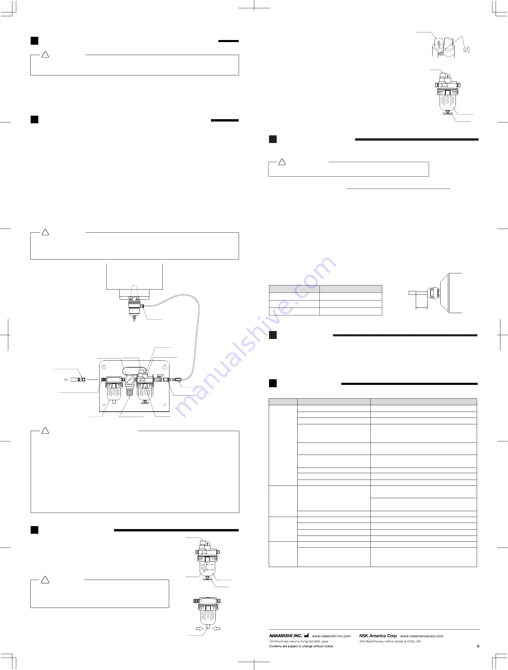
③Adjusting the Oil Drip Rate (
;<
)
Run HTS1501S at the specified air pressure and adjust the oil drip
rate to the recommended rate by turning the Oil Drip Rate Adjusting
Screw.(About 30 to 40 drips/min) Turn the screw counterclockwise
to increase the rate and clockwise to decrease. When using non-
NAKANISHI lubricator, adjust the oil drip rate to about 1-3 drips/min.
④Remove Oil and Moisture Regularly (
;=
)
Remove and replace the oil in the Reservoir once a month, to
ensure a pure oil source for the motor. Moisture may collect and mix
with the oil in the Reservoir and damage the motor. Open the Drain
Valve at the bottom of the reservoir by turning it counterclockwise.
⑤Oil
Liquid paraffin ISO VG15 is recommended.
Increase
Decrease
Oil Filler
Oil Reservoir
Drain Valve
9
% %
①The proper surface speed for vitrified grindstones is 600-1,800m/min.
10
2 %
HTS1501 is designed to prevent coolant from entering the motor/spindle by using the air used for
driving the turbine as an air purge. Never spray coolant directly on the HTS1501S main body,
because coolant may enter the motor/spindle. Coolant or foreign particle contamination of the
spindle,s internal components will dramatically shorten bearing life.
②Do not exceed 13㎜ overhang for mounted grindstones. In case overhang must exceed 13㎜
reduce the motor speed in accordance with Fig.19.
③Do not use tools with bent or broken shanks, cracks or excessive runout.
④Dress the grindstone prior to use.
⑤For grinding the maximum depth of cut should not exceed 0.01㎜ radially or axially. Reciprocate the
tool several times after each in feed step.
⑥Always operate tools within the tool manufacturer s recommended speed limits. Use of a tool
outside of the manufacturer s recommended speed limits could cause damage to the spindle and
injury to the operator.
⑦Keep the tool shank and collet clean. If contaminants are left in the collet they can cause excessive
runout and damage the tool and spindle.
⑧Do not drop or hit spindle.
Surface Speed(m/min)=
3.14×Diameter(㎜)×rotation Speed(min
−1
)
1,000
Overhang(㎜)
20
25
50
Speed(min
−1
)
N×0.5
N×0.3
N×0.1
Table1.Overhang and Speed
N:Max.Operating Speed at 13㎜ Overhang
8 / >6
!
% 2#3"
;?
2014.09.20 002
Hose Connector
;,
Easy Joint
Side dome
Oil Filler Cap
Filter Joint
Air supply Hose
To Air Compressor
Air Supply Hose Connector
Air Filter
Regulator Knob
Lubricator
8
' ( 3
①Oil Volume (
;
)
Check the oil volume at least once a week. If the oil level is low,
fill to the upper limit. If the oil level is above the upper limit,
remove the excess oil. Take care not to over or under fill the oil
reservoir as this can cause the oil delivery rate to vary.
②Moisture in the Air Filter (
;@
)
Drain moisture from the Air Filter by pushing the Drain Valve
sideways.
.
! %
3 ; %
!
Oil filler Cap
Oil Reservoir
Drain Valve
Oil Gauge
Upper Oil Limit
Lower Oil Limit
Push Right & Left
Drain Valve
% 2#3"
;@
;
Side Dome
Oil Drip Rate
Adjusting Screw
;<
;=
Pressure Gauge
Oil Drip Rate
Adjusting Screw


