

Pull
Push
Loosen
Electric Connector
Cap
Air Cap
Ait Joint
Quick Release
Ring
①
Insert and Clamp the HES Brushless Motor Spindle to the
main spindle of the machining center.
②
Remove the Electric Connector Cap from the HES
Brushless Motor Spindlee by turning counterclockwise
(Fig. 20).
③
Remove the Air Cap from the HES Brushless Motor
Spindle's Air Joint (Fig. 20).
④
Install the
ȭ
4mm air hose on the HES Brushless Motor
Spindle's Air Joint (Fig. 21).
⑤
Detach the plug cap for motor cord and install the motor
cord to the HES Brushless Motor Spindle's plug. Please
make sure to align the pin on the plug and the groove on
the motor cord connector. Turn the motor cord connector
clockwise to tighten (Fig. 21, 22).
⑥
Fixture the Emergency Connector in the machine. Route
the motor cord and air hose and hold them securely with
enough slack to allow for quill travel. The Emergency
Connector should be positioned horizontally and the air
hose should not have any severe bends. Make sure air
can pass freely through the air hose. If the motor cord and
air hose are not held properly, the emergency connectors
may not separate properly in an emergency (Fig. 23).
Fig. 20
Spindle Housing
Motor Cord Connector
Alignment Hole
Alignment Pin
Insert
Tighten
Motor Cord
Air Joint
Plug
Fig. 21
Fig. 22
Emergency Connector
Emergency Air Joint
Bolt
Fig. 23
Block
(Not Provided)
(Accessories)
Lock Bar
Fig. 24
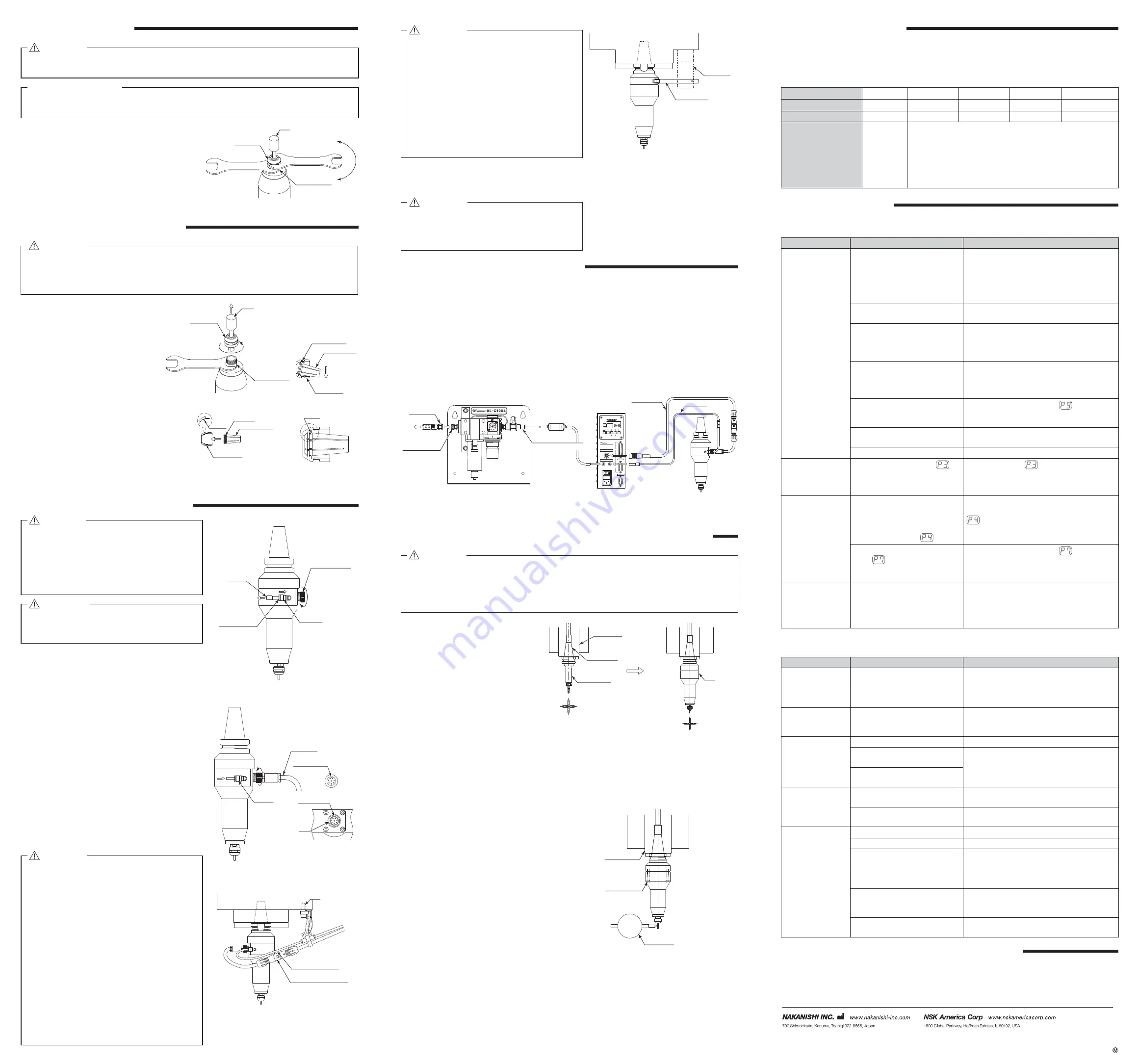
①
Connect the Motor Cord and Air Hose as shown in Fig. 25.
②
An Air Line Kit such as NAKANISHl'S (AL- C1204) must be used. The CONTROLLER and the HES Brushless
Motor Spindle must be supplied with clean, dry air regulated to between 0.25MPa - 0.3MPa Connect the output
of the Air Line Kit to the CONTROLLER's Air In connector. If you are not using NAKANISHl'S Air Line Kit, you
must use a regulator and air
¿
lter or dryer to supply clean, dry, regulated air to the CONTROLLER and the HES
Brushless Motor Spindle.
Water contamination in the air will cause damage to the Brushless motor and spindle.
※
For details of the operation and connections of the CONTROLLER and Air Line Kit please refer to their
respective Operation Manuals.
③
Do not attempt to start the HES Brushless Motor Spindle until you have completed and double checked all the
procedures described in this Operation Manual. Absolutely DO NOT ROTATE the MACHINE'S MAIN SPINDLE
after installing the HES Brushless Motor Spindle.
Motor Cord
Air Hose
CONTROLLER
To Air Compressor
SERIAL I/F
LOAD
RUN
×
1000min
-1
WARNING
SPEED
UP
DOWN
ERROR
RESET
GEAR
CTRL
DIR
START
STOP
AUTO
FWD
MANUAL
REV
NE260
E3200 SERIES CONTROL UNIT
MOTOR
AIR
A
B
EXT I/O
IN
OUT
Primary Joint
Connector for
Air Hose
Connection
Hose
Secondary Joint
ȭ
6 One - Touch Joint
Fig. 25
①
To
¿
nd the main spindle's center, mount
a tool in a highprecision end mill holder
and machine the pattern described
below and measure the center. Or use
a 1/4" collet chuck (Option) and mount
an edge
¿
nder in the collet chuck to
determine the true centerline of the HES
Brushless Motor Spindle.
②
To adjust the HES centerline, mount
the HES Brushless Motor Spindle in the
machining center's quill and use a dial
gauge on a test pin. Loosen the six bolts
that hold the taper housing together,
slightly and tap out the X-Y eccentricity.
Rotate the machining center's spindle by
hand to Main Spindle verify concentricity.
(Fig. 28)
Main Spindle
Spindle Taper
Tooling Holder
Mill an X-Y cross pattern in
a scrap piece and measure
the X-Y intersection.
Mount the HES Brushless Motor
Spindle in the quill and mill the same
cross pattern with a smaller diameter
tool inside the previously milled
pattern. Measure the difference in the
X-Y intersections.
Fig. 26
Fig. 27
Main Spindle
Dial Gauge
(6pcs.)
Mounting Bolt
Fig. 28
During transportation, storage or installation, the grease inside the bearings will settle. If the spindle is suddenly
run at high-speed, the grease will be ejected from the bearings, causing excessive heat that will cause bearing
damage. After installation, repair, initial operation, or long periods of non operation, please follow the break-in
procedure detailed in Table 2.
Tool
12
14
Chuck Nut
Spindle Shaft
Loosen
①
Remove the tool according to the section
" 7. CHANGING THE TOOL" procedure
above and remove chuck nut assembly.
(Fig. 16)
②
The collet chuck and chuck nut are
secured by a groove in the collet chuck
and a
À
ange in the chuck nut. To remove
the collet chuck hold the chuck nut in one
hand and push diagonally down on the
collet chuck. The collet chuck should be
released (Fig. 17).
③
To install the collet chuck, hold the collet
chuck at a slight angle, and insert it into
the chuck nut (Fig. 18).
Press the collet chuck in the chuck nut by
positioning the collet chuck in the chuck
nut and pressing down on
À
at surface.
(Fig. 17)
Be sure to fully engage the latch inside
the chuck nut into the groove on the collet
chucks outer circumference area (Fig. 19).
Fig. 16
Groove
Latch
Collet Chuck
Chuck Nut
Latch
Collet Chuck
Wrench Seat
Chuck Nut
DOWN
Fig. 18
Fig. 19
8
. REPLACING THE COLLET CHUCK
CAUTION
When installing the collet chuck into the chuck nut, be sure to fully engage the latch inside the
chuck nut to the groove on the collet chucks outer diameter area. In addition, remember that if the
collet chuck is attached without being engaged with the latch of the chuck nut, the collet chuck
cannot be removed and this may cause damage to the collet chuck or the spindle.
Fig. 17
9
. INSTALLATION INTO THE MACHINE
DANGER
Do not rotate the machining center's main spindle
with the HES Brushless Motor Spindle installed.
Rotating the machining center's main spindle with
the HES Brushless Motor Spindle installed
can cause the motor cord to become tangled and
pull the control unit off it is mounting. This may
cause lead to a big accident.
WARNING
Whenever installing a Brushless Motor Spindle to a
¿
xed base, ensure that the
¿
xed base is grounded
in order to avoid risk of an electric shock.
CAUTION
・
When not using the HES Brushless Motor Spindle
please replace the Electric Connector Cap and air
cap to protect the connectors from contaminants
with HES Brushless Motor Spindle body. And reset
the plug cap for motor cord to motor cord.
・
Check that the Motor Cord Connector, Air Hose
and Emergency Connector have been tightened
properly before operation.
・
DO NOT separate the emergency connector
manually.
It is not a quick disconnect connector. Emergency
System: If the machine's main spindle is rotated
by mistake, the Emergency Connector on the
motor cord will separate. If the hanger for the
Emergency Connector is too loose the Emergency
Connector can slip out of position during high
speed rotation and cause the Emergency System
to malfunction.
Please check the integrity of the Emergency
Connector and suspension prior to use.
10
. CONNECTING TO THE CONTROLLER
11
. THE HES BRUSHLESS MOTOR SPINDLE CENTERING ALIGNMENT
CAUTION
It is important to align the HES centerline to the machining center's centerline prior to using the
HES Brushless Motor Spindle. The HES Brushless Motor Spindle and taper housing are precision
machined to the exacting tolerances of the applicable standard for each taper. However, since no
tolerance is +0, - 0 it could be dif
¿
cult to initially achieve perfect centerline alignment just by hand
loading the spindle. Please follow the steps below to ensure proper centerline alignment.
HES
12
. BREAK-IN PROCEDURE
Steps
1
2
3
4
5
Rotation Speed (min
-1
) (rpm)
12,000
24,000
32,000
40,000
50,000
Rotation Time (min)
15
10
10
10
10
Items to Check
No Abnormal
Noises.
The spindle housing temperature during the break-in process should
not exceed 20 degrees C (36 degrees F) above ambient temperature.
Should the spindle exceed this limit, rest the spindle for at least 20
minutes and re-start the break in procedure from the beginning. If
the housing temperature rises again and exceeds 20 degrees C (36
degrees F) above ambient temperature, check the spindle and motor
for proper installation.
Table 2.
Trouble
Cause
Inspection / Corrective Action
Motor does not run.
Power is not supplied.
・
Make sure to turn ON the Main Power Switch on
the front (rear) of the CONTROLLER.
・
Insert the power cord plug correctly into the Main
Power Inlet with Power Supply Fuses of the
CONTROLLER.
・
Check if a fuse is blown.
Motor Cord Plug is not connected to
the Motor, CONTROLLER.
Connect the Motor Cord plug correctly to the Motor
and CONTROLLER.
Control Button (CTRL) is set to
Manual mode but trying to start
with an External Command Signal
through Input / Output Connector A.
Start with the Start / Stop Button (START/STOP),
or set the Control Button (CTLR) on the Control
Panel to Auto mode.
Control Button (CTRL) is set to Auto
mode but trying to manually start
with the Start Button (START/STOP)
on the Control Panel.
Start with an External Command Signal or set the
Control Button on the Control Panel to Manual
mode.
Emergency Stop Signal on External
Input / Output Connector B is OFF
(Open).
Check the setting of parameter
.
An Error has occurred.
(Error LED is lit.)
Check and correct the source of the Error Code.
Low air pressure.
Adjust to the air pressure 0.25 ~ 0.3MPa.
Can not set the
increase or decrease
of the Motor Rotation
Speed.
Motor Fixed Speed is set in
parameter. Turn this Parameter OFF
to allow rotational speed changes.
Release parameter
.
Can not set the
motor speed to its
maximum allowable
speed.
Either the required speed value is
higher than the maximum rotation
speed of the motor, or the upper
limit of the rotational speed has
been set in parameter
.
Set the Maximum Rotation Speed to a value less
than the Motor Rotation Speed set in Parameter
.
Air Input Monitoring Override is set
in the
parameterto ON and the
motor's maximum speed has been
limited to 30,000 min
-1
(rpm).
Check the setting of parameter
.
A blinking dot appears
on Digital Speed
Indicator. Cannot set
the desired rotation
speed.
Gear Ratio is set to a value other
than "1.0 ".
Check the setting of Gear Ratio.
< CONTROLLER or Motor >
13
. TROUBLESHOOTING
If a problem or concern occur, please check the following items prior to consulting your dealer.
Refer to the E3000 CONTROLLER Operation Manual.
Trouble
Cause
Inspection / Corrective Action
Spindle does not
rotate or rotate
smoothly.
The spindles ball bearings have
been damaged.
Replace the ball bearings.
(Return to NAKANISHI dealer service.)
The motor has been damaged.
Replace the motor.
(Return to NAKANISHI dealer service.)
Overheating during
rotation.
Cutting debris has contaminated the
ball bearings, and the ball bearings
are damaged.
Replace the ball bearings.
(Return to NAKANISHI dealer service.)
Abnormal vibration or
noise during rotation.
The tool shank is bent.
Replace the tool.
Cutting debris has contaminated the
ball bearing.
Replace the ball bearings.
(Return to NAKANISHI dealer service.)
The spindles ball bearings have
been damaged.
Tool slippage.
Collet chuck or chuck nut are not
correctly installed.
Check and clean the collet chuck and chuck nut.
Reinstall the collet chuck and chuck nut.
The collet chuck and the chuck nut
are worn.
Replace the collet chuck and chuck nut.
High run-out.
The tool is bent.
Change the tool.
Chuck nut is not correctly installed.
Secure the collet chuck and the chuck nut correctly.
The collet chuck and the chuck nut
are worn.
Replace the collet chuck and the chuck nut.
Inside of the spindle is worn.
Replace the spindle shaft.
(Return to NAKANISHI dealer service.)
Contaminants inside the collet
chuck and the chuck nut or the
spindle.
Clean the collet chuck, chuck nut and the inside
of the taper and spindle.
The spindle ball bearings has been
damaged.
Replace the ball bearings.
(Return to NAKANISHI dealer service.)
< Spindle >
14
. DISPOSAL OF THE BRUSHLESS MOTOR SPINDLE
When disposal of a Brushless Motor Spindle is necessary, follow the instructions from your local government
agency for proper disposal of industrial components.
Contents are subject to change without notice.
7
. CHANGING THE TOOL
①
Set the provided 12mm wrench on the spindle.
②
Place the provided 14mm wrench on the chuck
nut and turn it counterclockwise to loosen the
collet chuck and remove the tool. (The
¿
rst turn will
loosen the chuck nut, but the tool will not release
and turning will become stiff. Keep turning through
the stiffness and the collet chuck will open.)
③
Clean the collet chuck and chuck nut, then insert
the new tool and tighten the collet chuck by turning
clockwise. Do not overtighten.
CAUTION
Do not tighten the collet chuck without inserting a tool or dummy bur, as this will damage the
collet chuck, spindle or chuck nut, causing dif
¿
culty removing the collet chuck.
RECOMMENDATION
Please set the cutting tools to minimize the overhang amount. 13mm is the maximum amount of
overhang to maintain high accuracy and safety.
14
12
Loosen
14
12
Tighten
Tool
Chuck Nut
Spindle Shaft
Fig. 15
⑦
Installation of the provided lock bar
Screw the lock bar into the tapped hole on the spindle
housing as shown in Fig. 24
CAUTION
The lock bar is not intended to stop the main
spindle from rotating ; it is only intended to be
used as a precautionary measure. If it is not
needed, it does not need to be installed.
CAUTION
・
If the Emergency Connector is separated, check
the motor cord and air hose for damage, Ieaks,
rips, torn insulation or any other damage before
reconnecting the Emergency Connector. If the
Air Emergency Connector is separated, you
may reconnect using a small dab of Super Glue
to reattach it. Check air system for leaks and if
everything checks ok you can proceed with use.
If problems exist in either the Air Emergency
Connector or the Motor Cord Emergency
Connector please send the unit to NAKANISHI
for service. Do not disconnect the Air Emergency
connector expect in an emergency.
2014.09.20 002


