background image

9

10

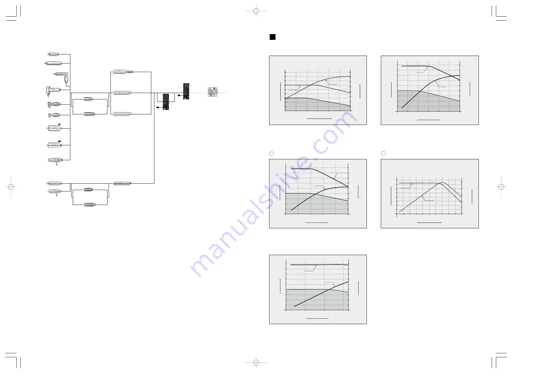
TORQUE CHARACTERISTICS

5

Spindle  NR-2551

Speed Reducer
ARG-2516N (1 / 16 Reduction)

Speed Reducer
ARG-2504N (1 / 4 Reduction)

Brushless Motor
(Cord with Quick Disconnect)
EM25N-5000-J4

Lever Type
Spindle 
NRR-2651

50,000min

-1

(NR-453E)

40,000min

-1

(NR-403E)

20,000min

-1

(RAX-271E)

5,000min

-1

(RAX-71E)

1,000

~

60,000min

-1

1,000

~

60,000min

-1

1,000

~

50,000min

-1

1,000

~

32,000min

-1

60,000min

-1

7,490min

-1

7,490min

-1

13,330min

-1

50,000min

-1

50,000min

-1

50,000min

-1

50,000min

-1

60,000min

-1

Spindle
NR-453E / NR-403E

Spindle  NR-3060S

Motor Cord
EMCD-3000

90º Angle Spindle
RAS-151E
(1/2.67)

90º Angle Spindle
RAX-271E (1/1.5)
RAX-71E (1/6)

90º Angle Spindle
RA-271E (1/1.5)

90º Angle Spindle
RA-151E (1/2.67)

Automatic Tool
Replacement Spindle
NR50-5100 ATC

Automatic Tool
Replacement Spindle
NR40-5100 ATC

Brushless Motor
EM-3060

Brushless Motor
EM-3060J
EM-3060J-2M

Motor Cord
 (Cord with Quick
  Disconnect)
EMCD-3000J

Brushless Motor
EM-3030J
EM-3030J-2M

Motor Cord
 (Cord with Quick
  Disconnect)
EMCD-3000J

Speed Reducer
ARG-011E (1 / 4 Reduction)

Speed Reducer
ARG-021E (1 / 16 Reduction)

Lever Type
Spindle 
NRR-3060

Open and Close Lever

Open and
Close Lever

30,000min

-1 

(

*

2)

7,500min

-1 

(

*

1)

30,000min

-1 

(

*

2)

1,870min

-1 

(

*

1)

30,000min

-1 

(

*

2)

7,500min

-1 

(

*

1)

30,000min

-1 

(

*

2)

1,870min

-1 

(

*

1)

Compressor

100V~
240V

100V~
240V

Air Line Kit  
AL-0201

Selector Unit
NE261

Control Unit
NE260
NE260-OP1

*

Cooled-air is supplied.

*

Single motor can only be 

   operated at the same time. 
   No simultaneous operation.

1 : Maximum rotating speed at the cutting tool.
2 : Maximum allowable motor speed for the spindle.

*

*

(2) Modular Type

32

30

20

10

0

0

450

9

400

8

350

7

300

6

250

5

200

4

150

3

100

2

50

1

Continuous Duty Area

Output 

(W

)

Torque 

(

cN

. m

)

Speed ( x 10

min

-1

)

Torque

Output

(4) 32,000min

-1

Fig. 10

50

40

30

20

10

0

0

450

9

400

8

350

7

300

6

250

5

200

4

150

3

100

2

50

1

Output 

(W

)

Torque 

(

cN

. m

)

Speed ( x 10

min

-1

)

Continuous Duty Area

Torque

Output

(3) 50,000min

-1

EM25N-5000

HES510

4

1

3

5

2

6

7

8

0

5

10

35

15

25

20

30

40

45

50

50

100

200

150

0

250

Output

Torque

Torque 

(cN

.

m

)

Output 

(W

)

Speed ( x 10

min

-1

)

Fig. 9

Fig. 8

Output 

(W

)

1

0

2

3

4

5

6

7

8

9

20

30

40

50

60

70

80

300

350

400

250

200

150

100

50

0

Output

Continuous Duty Area

Torque

Torque 

(cN

. m

)

Speed ( x 10

min

-1

)

(1) 80,000min

-1

60

50

40

30

20

10

0

0

450

9

400

8

350

7

300

6

250

5

200

4

150

3

100

2

50

1

Output 

(W

)

Torque 

(

cN

. m

)

Speed ( x 10

min

-1

)

Continuous Duty Area

Torque

Output

(2) 60,000min

-1

Fig. 7

Fig. 6

Fig. 5

1

2

NE260̲K0581E̲e̲0905    09.9.22  1:16  AM    ページ 9

Summary of Contents for E3200 Series

Page 1: ... 09 05 003 A NE260 E3200 SERIES CONTROL UNIT OM K0581E ...

Page 2: ...re children may be present 11 DON T FORCE TOOL It will do the job better and safer at the rate for which it was designed 12 USE RIGHT TOOL Don t force tool or attachment to do a job for which it was not designed 13 WEAR PROPER APPAREL Do not wear loose clothing gloves neckties rings bracelets or other jewelry that might get caught in moving parts Nonslip footwear is recommended Wear protective hai...

Page 3: ...hen errors occur and error lamp flashes check and correct the cause of the malfunction before continuing use Failure to correct the problem will result in damage to the unit and motor 4 When the Warning Lamp on the control unit lights conditions exist that could result in dangerous operation Check operating conditions and continue use only after correcting the problem 5 Do not hit drop or subject ...

Page 4: ...r speed from 1 000 to 80 000 min 1 for EM 3080J and HES810 Using Cutting Capacity Motor Speed Area is from 20 000 to 80 000 min 1 Control to limit motor speed from 1 000 to 60 000 min 1 for EM 3060 EM 3060J EM30 S6000 EM25 S6000 and EM20 S6000 Control to limit motor speed from 1 000 to 50 000 min 1 for EM25N 5000 and HES510 Control to limit motor speed from 1 000 to 32 000 min 1 for EM 3030J EMA 3...

Page 5: ...000min 1 60 000min 1 60 000min 1 21 300min 1 21 300min 1 8 000min 1 50 000min 1 Brushless Motor Spindle EM30 S6000 Brushless Motor Spindle EM25 S6000 Brushless Motor Spindle EM20 S6000 Brushless Motor Spindle EMS 3060A Brushless Motor Spindle EMS 3060K Brushless Motor Spindle EMR 3008K Motor Cord Cord with Quick Disconnect EMCD 3000J Motor Cord Cord with Quick Disconnect EMCD 3000J Motor Cord Cord...

Page 6: ...and Close Lever 30 000min 1 2 7 500min 1 1 30 000min 1 2 1 870min 1 1 30 000min 1 2 7 500min 1 1 30 000min 1 2 1 870min 1 1 Compressor 100V 240V 100V 240V Air Line Kit AL 0201 Selector Unit NE261 Control Unit NE260 NE260 OP1 Cooled air is supplied Single motor can only be operated at the same time No simultaneous operation 1 Maximum rotating speed at the cutting tool 2 Maximum allowable motor spee...

Page 7: ...reen 2 Yellow and 1 Red Continuous operation is possible with up to all 3 green LED s lit If one of the yellow LED s is lit the motor spindle can only be run for a short time Please refer to PROTECT FUNCTION of this manual for allowable duration of high load operation When any of the yellow or red LED s are lit the warning LED Warning 20 will flash if this condition is continued beyond the allowab...

Page 8: ...nks and the Digital Speed Indicator 11 alternates between the warning code and the actual or preset speed depending on whether or not the motor spindle is rotating 21 Rotating LED RUN When the motor is rotating this LED will flash 1 Push on the clips on the top and bottom of the fuse holder and remove the fuse holder and fuses 2 Remove the bad fuse or fuses and replace with the proper type and rat...

Page 9: ...ly the Rubber Pad Provided is installed at the side of the air vents Install the control unit so the air vents are underneath the control unit When installing horizontally remove the 4 screws on the Control Panel and remount the panel at a 90 Angle Before removing the control panel be sure the Power Switch is OFF and remove the Power Inlet Cord 8 4 Proper Clearance When installing 2 or more contro...

Page 10: ...t joint 8 on the front of the control unit using the provided ø6mm to ø4mm adaptor 4 Regulate air pressure between 0 25 0 3MPa The system can be set to operate without cooling air Please see parameter setting to set this option Maximum speed is 30 000min 1 when not using cooling air Note It is not recommended to use the system in this manner for general machining This setting is only for light cut...

Page 11: ...ANISHI offers spindles with a wide variety of capabilities and specifications Please carefully check the product s specifications against the requirements of your application and verify suitability and safety prior to initial use WARNING When installing a motor spindle to a fixed base make sure the fixed base is grounded in order to avoid the risk of an electric shock REPLACING THE COLLET The span...

Page 12: ...1 000 min 1 80 equals 80 000 min 1 All the functions of the system can be controlled by input control signals to Input Output Connector A 3 Except setting gear ratio 13 17 15 OPERATION PROCEDURES 1 Select Control Mode Manual Auto Fig 31 2 Setting motor rotating direction gear ratio GEAR Motor Start Stop Motor Speed 2 1 Setting Manual Mode 1 Set motor rotating direction Push the motor rotating dire...

Page 13: ...Parameters section of this manual for details on reversing these signals 3 Setting other Motor Speed Parameters The following Motor Speed Parameters can also be preset Pin No Pin Name Description Input Output Signal Function 1 2 3 4 5 6 7 8 9 10 COM_1 DIR_IN CNT_IN RESET SEL1 RUN DIR_OUT ERR GND External Power Source for External Inputs Rotating Direction Signal Count Pulse Signal for setting Moto...

Page 14: ...onnected to both the sink and the source Voltage and Current Specifications Applied Voltage V max 30VDC Working Current Ip 100mA Use an external power source for output circuits It is recommended to use the same 24VDC power source used for input signals Please refer to Fig 35 for connections Fig 34 Fig 33 2 Fig 35 3 COM_1 START 24Vor0V 0Vor 24V DIR_IN RESET 500min SEL0 SEL1 UD_IN CNT_IN Potentionm...

Page 15: ...ed Emergency OFF Open When there is continuity OFF between PIN2 and PIN10 the selected motor is connected if no continuity the motor is disconnected or the motor cord is broken When there is continuity between PIN3 and PIN11 ON Closed Safety Relay is OFF System Stopped no continuity Safety Relay is OFF Open Normal Operation When there is continuity between PIN4 and PIN12 ON Closed Safety Relay is ...

Page 16: ...iers Use only shielded cables to minimize RF interference and noise Connect the shield to the plug cover Different makers use different names for the cover CAUTION To minimize RF interference and noise please keep the length of the cables as short as practical and route separate from power cables 3 Input Output Signal Connector Specifications 1 2 Output Signal PIN No 2 10 5 13 6 14 There are 3 kin...

Page 17: ...g air prior to use This will help prevent system errors that will result in undesired operating conditions When an Error Occurs the following events happen 1 Motor stops 2 The Error LED 19 will flash 3 Error Code listed in Table 3 will be displayed on the Digital Speed Indicator 11 4 An Error signal is output to the Error Signal PIN No 8 ERR of Input Output Connector CAUTION When the Warning LED 2...

Page 18: ...ises 30 000 10 Min 40 000 10 Min 4 5 6 50 000 15 Min 60 000 10 Min 80 000 10 Min Spindle Housing less than 20 C BREAK IN PROCEDURE Table 4 Steps 18 Spindle Housing no hotter than 20 C If hotter than 20 C stop for at least 20 minutes check installation and restart Break In procedure 7 Keep the tool shank and collet clean If contaminants are left in the collet they can cause excessive runout and dam...

Page 19: ...t and FWD Start signals Air Input monitoring override The system can be configured to operate without cooling air maximum speed is 30 000 min 1 Setting Motor Speed Control Signal There is the compatibility with E3000C Control unit about Motor Speed Control Signal When setting the Motor Speed Control Signal the maximum motor speed is 60 000min 1 When connecting to the motor spindle with the maximum...

Page 20: ...Push the Reset Switch to send the settings to memory will be displayed depending on the parameter being set 7 If you desire to set other parameters push the Motor Speed Adjustment Switch to select the parameter to be set 8 If you are finished setting parameters turn the Power Switch off Setting Fixed Motor Speed Allows the motor speed to be fixed Fixes the motor speed in both MANUAL and AUTO modes...

Page 21: ...o be set 7 If you are finished setting parameters turn the Power Switch off 6 Setting Maximum Motor Speed Allows the maximum motor speed to be set Fixes the motor speed in both MANUAL and AUTO modes Procedure 1 Push the Start Switch 2 is displayed This indicates that the Maximum Motor Speed cannot be set 3 Push the Start Switch 4 is displayed This indicates that the Maximum Motor Speed can be set ...

Page 22: ...n and the setting for or 15 Push the Start Switch 16 Display oscillates between and the setting for or 17 Push the Start Switch 18 Return to setting Parameter or push Error Reset Switch to finish 9 Setting Motor Speed Control Signal There is the compatibility with E3000C Control unit about Motor Speed Control Signal When setting the Motor Speed Control Signal the maximum motor speed is 60 000min 1...

Reviews: