15
n-SUB
11 Introduction
Naim loudspeakers are precision acoustic instruments that will only achieve optimal
performance if installed and set up carefully. Please read these instructions before
installing and using the n-SUB. Please also retain the packaging. The n-SUB is very
heavy and care should be taken when lifting or moving it. Do not connect the n-SUB
to the mains wall socket until all other connections are made. Take great care when
moving and handling the n-SUB that cables are not damaged by its floor spikes.
The
n-SUB
is an active sub-woofer primarily intended to be used in conjunction with
n-SATS
and the
n-CENT
in home theatre and multi-channel audio applications. The
n-SUB
can also be used however
with
n-SATS
in a stereo satellite/sub-woofer (2.1) loudspeaker system.
A variety of
n-SUB
set up parameters can be defined and stored as presets. These enable
n-SUB
performance to be adjusted for different programme material types, personal preferences and
listening levels etc (i.e Stereo or AV setups). Up to six presets can be stored. Preset selection or real-
time adjustment of
n-SUB
can be carried out from either its control panel or the remote handset.
Loudspeakers, like many hi-fi components, will take time to stabilise and “run-in” and can be
expected to improve with use even over a period of weeks. For this reason it is prudent not to finalise
positioning until they have been operating for at least one week.
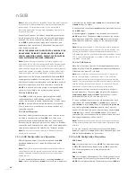
11.1 n-SUB Installation
11.1.1 n-SUB Positioning
In principle there is significant freedom of position of a sub-
woofer in a listening room. In practice, however, the performance
of the
n-SUB
will be fundamentally influenced by the room and
position in which it is located. Small changes of position, or the
resonant characteristics of items in the immediate vicinity of the
n-SUB,
can significantly influence its performance
.
Initially choose a site for the
n-SUB
along one of the walls of the
listening room well away, but not equi-distant, from the corners.
It is not necessary that the
n-SUB
be positioned along the same
wall as the main loudspeakers. Locate the
n-SUB
such that its
control panel is facing out from the wall. Leave a gap of between
100mm (4”) and 150mm (6”) between the rear panel (driver
panel) and the wall. Chose a solid, rather than a partition, wall
and keep the
n-SUB
clear of any significant resonant objects -
large furniture panels, heating radiators, etc.
The
n-SUB
is not magnetically shielded and should be kept
a minimum of 2m away from CRT displays (plasma, LCD or
DLP displays are not affected). Should a display suffer picture
distortion caused by the proximity of the
n-SUB
contact your
dealer or installer for advice.
The
n-SUB
amplifier is cooled by air flow entering through
perforations in its underside and exiting through a vent above the
display window. This air flow must not be restricted.
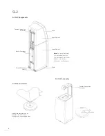
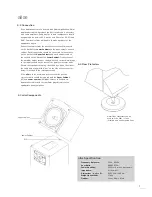
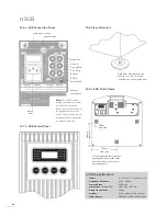
A cable clamp is supplied in the pack containing this manual
intended to hold the mains cable in position and to help prevent
it from being damaged by floor spikes. It can be fitted as
appropriate in any of the 3 positions shown in Diagram 11.9
depending on the positioning of the
n-SUB
relative to the wall
and mains socket.
11.1.2 n-SUB Floor Spikes
With the initial position decided begin
n-SUB
installation by
fitting the four
floor spikes
and
lock-nuts
to the underside of
the enclosure. Adjust the spike length to hold the
n-SUB
at least
20mm above the floor covering
Note:
If you intend to install the n-SUB on a non-carpeted floor the
spikes should be used in conjunction with Naim Floor Protectors
(see Diagram 11.8). Your retailer or distributor will be able to supply
Floor Protectors.
With the floor spikes fitted, but not tightened, place the
n-SUB
on the floor in the intended position. Adjust the spikes so that
the
n-SUB
does not rock and is level. Tighten each lock-nut
using a 10mm spanner.
Note:
With thick carpet and underlay it can be difficult to ensure
that the spikes are resting on the floor. Small slits cut into the carpet
once the loudspeaker position is finalised will help.
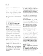
11.2 n-SUB Connections
The
n-SUB
carries a comprehensive set of signal and control
connections appropriate for integration with a variety of system
types and installations. The connection sockets (and mains
power input socket) can all be found on the underside of the
enclosure and are illustrated in Diagram 11.6. The
n-SUB
can be
turned up-side-down to aid access to the sockets.
DO NOT CONNECT n-SUB TO THE MAINS WALL SOCKET UNTIL
ALL CONNECTIONS ARE MADE AND IT IS RETURNED TO AN
UPRIGHT POSITION. TAKE GREAT CARE WHEN RETURNING
THE N-SUB TO THE UPRIGHT POSITION THAT CABLES ARE NOT
DAMAGED BY THE FLOOR SPIKES.
11.2.1 n-SUB Inputs
The
n-SUB
provides one mono and one stereo line level input on
RCA Phono sockets along with one stereo set of “speaker-level”
4mm input sockets.
The mono line level input should be used for AV systems where
an AV processor provides a mono sub-woofer (LFE) output.
The stereo line level input should be used when only an auxiliary
stereo output is available from, for example, a preamplifier. The
stereo channels are combined to mono within the
n-SUB
.
Note:
Do not use an amplifier “tape output” to connect to Input
2. The volume level from tape outputs does not vary with volume
control position.

