background image

23.  Battery Disposal 

- When disposing of used batteries, please comply with 

governmental regulations or environmental public instruction’s rules that apply in 
your country or area.

24.  Safety Check 

- Upon completion of any service or repairs to this product, ask the 

service technician to perform safety checks to determine that the product is in 
proper operating condition. 

25.  Wall or Ceiling Mounting 

- The product should be mounted to a wall or ceiling 

only as recommended by the manufacturer.

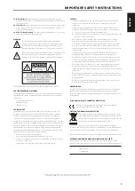
WARNING

The lightning flash with arrowhead symbol, within an equilateral 
triangle, is intended to alert the user to the presence of uninsulated 
“dangerous voltage” within the product’s enclosure that may be of 
sufficient magnitude to constitute a risk of electric shock to persons

The exclamation point within an equilateral triangle is intended to alert 
the user to the presence of important operating and maintenance 
(servicing) instructions in the literature accompanying the appliance.

THE EQUIPMENT MUST BE CONNECTED TO AN EARTHED MAINS SOCKET-OUTLET.

CAUTION REGARDING PLACEMENT 

To maintain proper ventilation, be sure to leave a space around the unit (from the 
largest outer dimensions including projections) than is equal to, or greater than 
shown below. 


Left and Right Panels: 10 cm 


Rear Panel: 10 cm 


Top Panel: 10 cm 

FCC STATEMENT

This equipment has been tested and found to comply with the limits for Class 
B digital device, pursuant to Part 15 of the FCC Rules. These limits are designed 
to provide reasonable protection against harmful interference in a residential 
installation. This equipment generates, uses, and can radiate radio frequency 
energy and, if not installed and used in accordance with the instructions, may cause 
harmful interference to radio communications. However, there is no guarantee that 
interference will not occur in a particular installation. If this equipment does cause 
harmful interference to radio or television reception, which can be determined 
by turning the equipment off and on, the user is encouraged to try to correct the 
interference by one or more of the following measures:

• 

Reorient or relocate the receiving antenna.

• 

Increase the separation between the equipment and receiver.

• 

Connect the equipment into an outlet on a circuit different from that to which 
the receiver is connected.

• 

Consult the dealer or an experienced radio TV technician for help.

CAUTION
• 

Changes or modifications to this equipment not expressly approved by NAD 
Electronics for compliance could void the user’s authority to operate this 
equipment.

• 

This device complies with Part 15 of the FCC Rules / Industry Canada licence-
exempt RSS standard(s). Operation is subject to the following two conditions: 

This device may not cause harmful interference, and 

This device must accept any interference received, including interference that 
may cause undesired operation.

• 

Under Industry Canada regulations, this radio transmitter may only operate 
using an antenna of a type and maximum (or lesser) gain approved for the 
transmitter by Industry Canada. To reduce potential radio interference to other 
users, the antenna type and its gain should be so chosen that the equivalent 
isotropically radiated power (e.i.r.p.) is not more than that necessary for successful 
communication.

• 

To prevent electric shock, match wide blade of plug to wide slot, fully insert.

• 

Marking and rating plate can be found at the rear panel of the apparatus.

• 

To reduce the risk of fire or electric shock, do not expose this apparatus to rain or 
moisture. The apparatus shall not be exposed to dripping or splashing and that 
no objects filled with liquids, such as vases, shall be placed on apparatus. 

• 

Mains plug is used as disconnect device and it should remain readily operable 
during intended use. In order to disconnect the apparatus from the mains 
completely, the mains plug should be disconnected from the mains socket outlet 
completely. 

• 

Battery shall not be exposed to excessive heat such as sunshine, fire or the like.

• 

Danger of explosion if battery is incorrectly replaced. Replace only with the same 
or equivalent type.

• 

An appliance with a protective earth terminal should be connected to a mains 
outlet with a protective earth connection.

MPE REMINDER

To satisfy FCC/IC RF exposure requirements, a separation distance of 20 cm or more 
should be maintained between the antenna of this device and persons during 
device operation. To ensure compliance, operations at closer than this distance is not 
recommended. 

IF IN DOUBT CONSULT A COMPETENT ELECTRICIAN.

This product is manufactured to comply with the radio interference 
requirements of EEC DIRECTIVE 2004/108/EC.

NOTES ON ENVIRONMENTAL PROTECTION

At the end of its useful life, this product must not be disposed of with 
regular household waste but must be returned to a collection point for 
the recycling of electrical and electronic equipment. The symbol on the 
product, user’s manual and packaging point this out. 

The materials can be reused in accordance with their markings. 

Through re-use, recycling of raw materials, or other forms of recycling of old products, 
you are making an important contribution to the protection of our environment. 

Your local administrative office can advise you of the responsible waste disposal point. 

RECORD YOUR MODEL NUMBER (NOW, WHILE YOU CAN SEE IT) 

The model and serial number of your new C 368 are located on the back of the 
cabinet. For your future convenience, we suggest that you record these numbers here: 


Model number :    . . . . . . . . . . . . . . . . . . . . . . . . . . . . . . . . . . . . . . . . . .


Serial number :  . . . . . . . . . . . . . . . . . . . . . . . . . . . . . . . . . . . . . . . . . . .

IMPORTANT SAFETY INSTRUCTIONS


NAD is a trademark of NAD Electronics International, a division of Lenbrook Industries Limited

Copyright 2019, NAD Electronics International, a division of Lenbrook Industries Limited

3

ENGLISH

FR

ANÇ

AIS

ESP

AÑOL

IT

ALIANO

DEUT

SCH

NEDERL

ANDS

SVENSK

A

РУ

ССКИЙ

Summary of Contents for C 368

Page 1: ...ENGLISH FRANÇAIS ESPAÑOL ITALIANO DEUTSCH NEDERLANDS SVENSKA РУССКИЙ Owner s Manual C368 Hybrid Digital DAC Amplifier ...

Page 2: ... Electrical Code ANSI NFPA 70 provides information with regard to proper grounding of the mast and supporting structure grounding of the lead in wire to an antenna discharge unit size of grounding conductors location of antenna discharge unit connection to grounding electrodes and requirements for the grounding electrode NOTE TO CATV SYSTEM INSTALLER This reminder is provided to call the CATV syst...

Page 3: ...interference received including interference that may cause undesired operation Under Industry Canada regulations this radio transmitter may only operate using an antenna of a type and maximum or lesser gain approved for the transmitter by Industry Canada To reduce potential radio interference to other users the antenna type and its gain should be so chosen that the equivalent isotropically radiat...

Page 4: ...and hold both front panel s a SOURCE s buttons until the display shows FACTORY RESET Release both a SOURCE s buttons afterwards IMPORTANT SAFETY INSTRUCTIONS 2 INTRODUCTION GETTING STARTED 4 WHAT S IN THE BOX 4 CHOOSING A LOCATION 4 RESTORING C 368 TO ITS FACTORY DEFAULT SETTINGS 4 IDENTIFICATION OF CONTROLS FRONT PANEL 5 REAR PANEL 6 MDC CLASSIC UPGRADE SLOTS 8 MDC HDM 2 8 DD USB 2 0 8 MDC BluOS ...

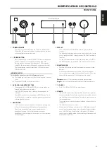
Page 5: ...personal stereo jack plugs 5 DISPLAY Show visual and menu information according to the selected settings The following Main menu options are shown in the display Source Setup Settings and BluOS Setup available if MDC BluOS module is installed Use the SR 9 remote control or front panel navigation d f a s and ENTER buttons to go through menu options and selections 6 REMOTE SENSOR Point the SR 9 remo...

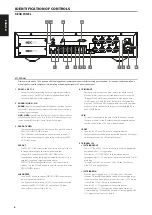
Page 6: ...cialists with respect to their compatibility to the C 368 s IR features IR IN This input is connected to the output of an IR infrared repeater Xantech or similar or the IR output of another compatible device to allow control of the C 368 from a remote location IR OUT Connect IR OUT to the IR IN jack of a compatible device Command and control the linked compatible device by directing its own remote...

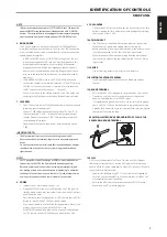
Page 7: ... connect and no loose strands of speaker wire 8 POWER Supplies the AC mains power to the C 368 When the POWER switch is set to ON position the C 368 goes to standby mode as shown by the amber status condition of the front panel Power indicator Press the front panel Standby button or SR 9 s remote control s ON button to switch ON the C 368 from standby mode If you do not intend to use the C 368 for...

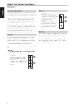
Page 8: ...so support both features are interconnected with C 368 via HDMI connection If an ARC connection is established the front panel display will show HDMI ARC IMPORTANT Ensure that ARC connected devices to C 368 have their audio settings set to PCM only A HDMI OUT Connect to corresponding HDMI port of HDTV projector with HDMI input or TV that supports HDMI CEC ARC B HDMI 1 3 Connect to the HDMI OUT con...

Page 9: ...ector 8 inAMPmodewill nowcorrespondtoBluetoothsourcewhileinputselector 9 willbeunassigned Refertoexamplebelow If you installed the optional MDC BluOS or MDC HDM 2 module the unassigned input selector 9 button will be allocated to BluOS or HDMI 1 source refer to MDC BluOS or MDC HDM 2 installed column below If you installed both optional MDC HDM 2 and MDC BluOS modules you have to disable two or mo...

Page 10: ... RPT Repeat track file or whole disc PROG Enter or exit program mode CLEAR Delete programmed track file CD Select CD as the active source USB Select USB as the active source OPT Select optical input as the active source SRC Toggle to select desired SRC mode TUNER CONTROL for use with NAD AM FM DAB Tuner Set the DEVICE SELECTOR to TUN in order to gain access to these buttons Refer to the correspond...

Page 11: ...ess ENTER while still holding down the device button CD The CD device selector will flash once to indicate that the library input is successful Both the device selector button CD and ENTER can now be released RESET THE SR 9 TO ITS DEFAULT SETTINGS The SR 9 can be restored to its factory settings including default libraries by the following procedures 1 Press and hold ON and DELETE CLEAR buttons fo...

Page 12: ...e NAD Remote App from the respective App stores of Apple iOS devices iPad iPhone and iPod and Android devices USING THE NAD REMOTE APP After downloading the NAD Remote App from the App store ensure that the following setup conditions for the C 368 are implemented Bluetooth antenna installation connection is secured and tight Ensure that your C 368 is powered up and ready From the selectable front ...

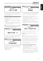
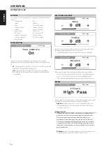
Page 13: ...n the current character The name can be as long as fourteen characters 3 Repeat steps 1 and 2 for each character in sequence 4 Complete the renaming process by pressing the ENTER button again to save the new source s input name The new Name will be shown in the display VOLUME CONTROL Volume control can be set to either Variable or Fixed level Variable Volume level is adjusted using the volume knob...

Page 14: ...he balance levels 0 dB level setting provides equal level to the left and right channels FILTERS Filters provide easy bi amplification or subwoofer integration by adding the required filters to redirect bass frequencies to the subwoofer High Pass Low pass signal up to 150 Hz is attenuated and over 150 Hz sent to the speakers This is based from 2nd order Linkwitz Riley Crossover Filter 150 Hz IMPOR...

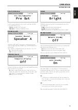
Page 15: ...ness NETWORK STANDBY Network Standby mode maintains network connection at standby mode with reduced system performance level On Network connection is maintained at standby mode Off Network connection is disconnected at standby mode Refer also to table below about OPERATING MODE TRIGGER POINTS AUTO STANDBY Auto Standby feature is an integral feature of C 368 that conforms to European ecodesign regu...

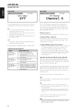
Page 16: ...hannel 0 to Channel 3 Press ENTER to select preferred IR Channel setting C 368 IR Channel is defaulted to Channel 0 To change the IR Channel on the SR 9 remote control Include a channel number before the library code For SR 9 library code 10 is the default library table for AMP device To select this AMP library table for Channel 0 retain the library code 10 or 010 If you want to load the AMP libra...

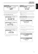
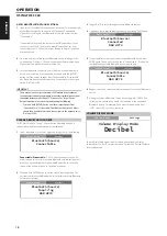
Page 17: ...her device Sink on the same Bluetooth network environment C368 AS A BLUETOOTH SINK Set BT Work Mode to Sink Initiate pairing of your Bluetooth device with C 368 by following below procedure 1 Ensure that the Bluetooth antenna is connected to the BT antenna terminal at the rear panel 2 Select Bluetooth as a Source Display shows Discoverable 3 Using your iOS or Android device go to Settings Bluetoot...

Page 18: ...ntenna terminal at the rear panel 1 Select Bluetooth as a Source Display could show any of the following Connectable Discoverable C 368 is open to connect or pair with other Source devices within the same Bluetooth network environment By default no connectable or discoverable Bluetooth devices will be shown as the unit hasn t gone to Inquiring mode yet 2 Press and hold ENTER button to set the unit...

Page 19: ...nfigured only at BluOS source mode With other sources the BluOS Setup menu options can be viewed only but not configurable INFO Display MAC address IP address BluOS version and other related information about the installed MDC BluOS module BluOS REBOOT Yes Restart MDC BluOS module No Maintain current settings SERVICE MENU There are two options for Service Menu BluOS Upgrade and BluOS Service BluOS...

Page 20: ...inuous output power into 8 ohms Bridge mode 300W ref 20 Hz 20 kHz atTHD 0 03 THD 20 Hz 20 kHz 0 03 250 mW to 80W 8 ohms and 4 ohms Signal to Noise Ratio 98 dB A weighted 500 mV input ref 1W out in 8 ohms Clipping power 95W at 1 kHz 0 1 THD Clipping power Bridge mode 315W at 1 kHz 0 1 THD IHF dynamic power 8 ohms 120W 4 ohms 200W 2 ohms 250W IHF dynamic power Bridge mode 8 ohms 500W 4 ohms 560W Pea...

Reviews: