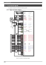
2.3 Connected signals
2-15
2.3.2 Safety inputs
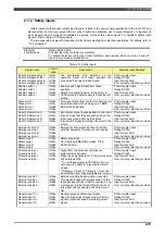
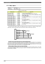
Safety inputs are redundant contact input signals, related to the power supply permission to the robot. When a
disconnection, short-circuit, ground fault or other trouble has detected due to signal disparity or diagnosis of
input signals, robot is stopped immediately by turning off the safety output signal. For details of safety input
signals, refer to Table 2.10 Safety inputs.
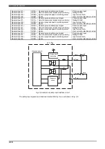
The two separate signals with redundant contact inputs must perform identical operations. For details, refer to
"1.3 Connection".
Electrical
specifications
Rating DC26V, 5mA
Connect the relay contacts (dry contacts).
To prevent defective contact and other problems, use a device which can turn on and off
the very small load specified above.
Table 2-13 Safety inputs
Signal name
Circuit
code
Description
Electrical specifications
Robot emergency stop 1+
Robot emergency stop 1-
Robot emergency stop 2+
Robot emergency stop 2-
IN1A+
IN1A-
IN1B+
IN1B-
The emergency stop switches on the
operation panel and teach pendant are
connected in series to these inputs.
Photo-coupler input
Rating DC26V
Input current 5mA
Over current protection provided
Enable switch 1+
Enable switch 1-
Enable switch 2+
Enable switch 2-
IN2A+
IN2A-
IN2B+
IN2B-
Enable switch signal input from teach
pendant.
Switch for supplying power to the motor in
TEACH mode. Power supply is ON at the ON
setting.
Photo-coupler input
Rating DC26V
Input current 5mA
Over current protection provided
Slave error 1+
Slave error 1-
Slave error 2+
Slave error 2-
IN3A+
IN3A-
IN3B+
IN3B-
Error input signal from another monitoring unit
since the second. When using only 1 RMU,
jumper these signals.
Photo-coupler input
Rating DC26V
Input current 5mA
Over current protection provided
Robot LS detection 1+
Robot LS detection 1-
Robot LS detection 2+
Robot LS detection 2-
IN4A+
IN4A-
IN4B+
IN4B-
Limit switch signal inputs installed in the robot
in such a way that they are pushed when the
robot axes move as far as their limits.
(Limit switch signal for cutting off power to the
motor.)
Photo-coupler input
Rating DC26V
Input current 5mA
Over current protection provided
Emergency stop 1+
Emergency stop 1-
Emergency stop 2+
Emergency stop 2-
IN5A+
IN5A-
IN5B+
IN5B-
Emergency stop signal input sent from the
external equipment (process control panel).
Photo-coupler input
Rating DC26V
Input current 5mA
Over current protection provided
Safety plug 1+
Safety plug 1-
Safety plug 2+
Safety plug 2-
IN6A+
IN6A-
IN6B+
IN6B-
Safety plug input.
On in Auto and MANUAL modes, Off in
TEACH mode.
Photo-coupler input
Rating DC26V
Input current 5mA
Over current protection provided
Protective stop 1+
Protective stop 1-
Protective stop 2+
Protective stop 2-
IN7A+
IN7A-
IN7B+
IN7B-
Signal from the process control panel
(external line controller).
When these signals are OFF, the motor power
will be turned OFF.
* To use these signals in TEACH mode, it is
necessary to enable in "Signal parameters"
screen.
* "Category 0 stop" or "Category 1 stop" can
be selected in the "Signal parameters" screen.
Photo-coupler input
Rating DC26V
Input current 5mA
Over current protection provided
External enable 1+
External enable 1-
External enable 2+
External enable 2-
IN8A+
IN8A-
IN8B+
IN8B-
External enabling device will be connected
This signal is used with enable switch on the
teach pendant as one of AND conditions. The
motor power will be turned ON when both of
this signal and the enable switch are turned
ON
Photo-coupler input
Rating DC26V
Input current 5mA
Over current protection provided
General input 11+
General input 11-
General input 12+
General input 12-
IN9A+
IN9A-
IN9B+
IN9B-
General-purpose safety input signal
Used for area select signal, stop monitoring
signal or playback speed monitoring select
signal.
Photo-coupler input
Rating DC26V
Input current 5mA
Over current protection provided
Summary of Contents for RMU20-20
Page 2: ......
Page 6: ...Contents 4 ...
Page 8: ......
Page 26: ...1 4 EC DECLARATION OF CONFORMITY FOR MACHINERY 1 18 NOTE ...
Page 68: ...2 9 Enabling RMU 2 40 NOTE ...
Page 70: ......
Page 100: ...3 4 Setting when a slider unit is used 3 30 NOTE ...
Page 102: ......
Page 138: ...4 4Approval 4 36 8 Approval is completed The following screen will be displayed ...
Page 144: ......
Page 154: ...5 4Trouble shooting 5 10 NOTE ...
Page 156: ......
Page 166: ...6 4Trouble shooting 6 10 NOTE ...
Page 168: ......
Page 189: ......


