


GT20 Control Wiring and Programming Manual
Part #C-00140
Rev. 10-7-16
2-6
120 VAC General Wiring
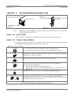
CHAPTER 2: 120 VAC GENERAL WIRING
Shut the installation site, branch Circuit Breaker OFF. Failure to do so may result
in serious personal or fatal injury. When uncertain whether power supply is
disconnected, always verify using a voltmeter.
All high voltage electrical connections must be made by licensed electricians according
to National and Local electrical codes/regulations.
Permanent wiring
shall be employed as required by local codes.
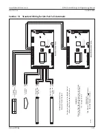
Keep all Incoming 120 VAC wiring separate from low voltage wiring within Header. 120
VAC Power wires must be routed (separate from other wiring) located near the top of
inside Header.
Ensure that the Grounding of the Electric Power Supply is installed/connected in a
proper way (especially the PE Cable from the Building Side).
Attention: Depending upon the installation, the Power Switch/Program Selector may have to be
installed on the opposite side of the Header. If 120 VAC Power wires must be installed
from Hinge Side of Header, ensure all wires are securely clipped to prevent pinching of
the wires during the Motor/Operator installation process.
Note: Please see “The Motor Connector Harness” chapter within this manual for wiring details.
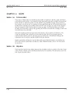
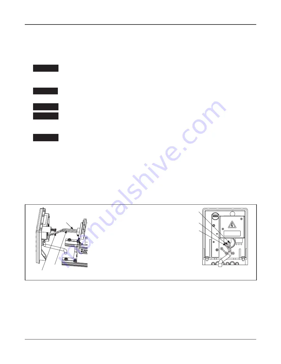
1.►Connect the Main Power Supply. Please see Figure 2-1.
2.►Mount the Side Cover.
DN 1177
~2 Cable
L = Live Wire
N = Neutral Wire (Common)
PE = Ground Wire
PE Cable
~1 Cable
Use Copper
Conductors Only
PC-ABS
0548-407
L Cable
N Cable
PE Cable
Figure 2-1
Connect the Power Supply
DANGER
WARNING
CAUTION
CAUTION
CAUTION