


(Revised 2012-05-01)
Page 117 of 169
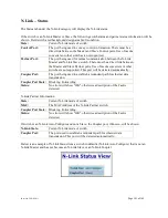
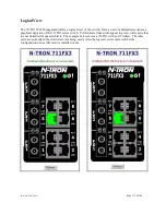
LogicalView
The 711FX3 Web Management offers a logical view of the switch. Here a user or administrator can see a
graphical depiction of the 711FX3 series switch. Ports that are linked will appear in green, while ports that
are not linked will appear in black. The example below shows a 711FX3 with port 5 linked. The other
ports are currently in the down state (not being used). Also, the logical view reveals whether the
configuration device (SD card) is installed or not.
Summary of Contents for 711FX3 Series
Page 1: ...711FX3 Managed Industrial Ethernet Switch User Manual Installation Guide ...
Page 11: ... Revised 2012 05 01 Page 11 of 169 CLEANING Clean only with a damp cloth ...
Page 33: ... Revised 2012 05 01 Page 33 of 169 Administration SNMP Continued ...
Page 37: ... Revised 2012 05 01 Page 37 of 169 DHCP Server Setup Profiles Continued ...
Page 40: ... Revised 2012 05 01 Page 40 of 169 DHCP Server Setup IP Maps Continued ...
Page 46: ... Revised 2012 05 01 Page 46 of 169 DHCP Relay Local IP Setup Continued ...
Page 52: ... Revised 2012 05 01 Page 52 of 169 Ports Configuration Continued ...
Page 83: ... Revised 2012 05 01 Page 83 of 169 The user can specify the manual router ports ...
Page 86: ... Revised 2012 05 01 Page 86 of 169 IGMP RFilter Continued Modifying rfilter port settings ...
Page 94: ... Revised 2012 05 01 Page 94 of 169 N Ring Advanced Configuration Continued ...
Page 119: ... Revised 2012 05 01 Page 119 of 169 If a Configuration Device is present that is presented ...