background image

(Revised 2010-11-15) 

SAFETY WARNINGS 


ELECTRICAL SAFETY 


WARNING: 

Disconnect the power cable before removing the end plates. 


WARNING:

 Do not operate the unit with the end plates removed. 


WARNING: 

Properly ground the unit before connecting anything else to the unit.  Units not properly 

grounded  may  result  in  a  safety  risk  and  could  be  hazardous  and  may  void  the  warranty.    See  the 
grounding technique section of this user manual for proper ways to ground the unit. 

 
WARNING: 

Do not work on equipment or cables during periods of lightning activity. 


WARNING:

 Do not perform any services on the unit unless qualified to do so. 


WARNING:

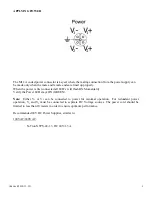
 Observe proper DC Voltage polarity when installing power input cables.  Reversing 

voltage polarity can cause permanent damage to the unit and void the warranty. 


HAZARDOUS LOCATION INSTALLATION REQUIREMENTS


1.


WARNING:

  Explosion hazard.  Do not remove or replace the device unless power has been switched off 

or the area is known to be non-hazardous. 

  
2.


WARNING:

  Explosion hazard.  Do not disconnect while the circuit is live or unless the area is known to 

be non-hazardous.

 
3.


WARNING:

  Explosion hazard.  Substitution of components may impair suitability for Class I, Division 2. 


4.


WARNING:

  Install only in accordance with Local & National Codes of Authorities Having Jurisdiction. 

 
5.


Class I, Div 2 installations require that all devices connected to this product must be UL listed for the area in 
which it is installed. 

 
6.


Limited Operating Voltage: 12-30V for Class I, Div 2 installations. 

 
7.


This  equipment  is  suitable  for  use  in  Class  I,  Div  2,  Groups  A,  B,  C,  and  D,  or  non-hazardous  locations 
only. 


Summary of Contents for 105M12

Page 1: ...Revised 2010 11 15 1 105M12 and 108M12 Industrial Ethernet Switches Installation Guide...

Page 2: ...Revised 2010 11 15 2 105M12 108M12 Industrial Ethernet Switches Installation Guide...

Page 3: ...r designations mentioned herein are trademarks of their respective owners The information contained in this document is subject to change without notice N TRON Corp makes no warranty of any kind with...

Page 4: ...sing voltage polarity can cause permanent damage to the unit and void the warranty HAZARDOUS LOCATION INSTALLATION REQUIREMENTS 1 WARNING Explosion hazard Do not remove or replace the device unless po...

Page 5: ...ch provides eight Category 5 compliant 10 100BaseTX connections with IP65 67 rated M12 D code connectors for high performance network design and hub repeater upgrades The switch is capable of auto neg...

Page 6: ...nst solid objects over 1 0mm e g wires 4 Protected against water sprayed from any direction Limited ingress permitted 5 Limited protection against dust ingress no harmful deposit 5 Protected against l...

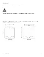
Page 7: ...e installation WARNING Never install or work on electrical equipment or cabling during periods of lightning activity BULKHEAD MOUNTING The following are the mechanical dimensions and drill hole placem...

Page 8: ...ections M12 A Coded Male Port Redundant Power Input 10 30VDC Green LED lights when Power is connected LED s The table below describes the operating modes LED Color Description ON Power is Applied OFF...

Page 9: ...nnected all LED s will flash ON Momentarily Verify the Power LED stays ON GREEN Note Either V1 or V2 can be connected to power for minimal operation For redundant power operation V1 and V2 must be con...

Page 10: ...connection has been completed To connect any other port to another Switch or Repeater use a standard Cat5 straight through or crossover cable Warning Creating a port to port connection on the same sw...

Page 11: ...cause harmful interference in which case the user will be required to correct the interference at his own expense INDUSTRY CANADA This Class A digital apparatus meets all requirements of the Canadian...

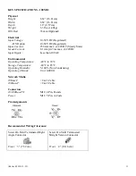
Page 12: ...C Input Ripple Less than 100 mV Environmental Operating Temperature 40 C to 80 C Storage Temperature 40 C to 85 C Operating Humidity 5 100 Non Condensing Operating Altitude 0 to 10 000 ft Network Medi...

Page 13: ...0 7ms max 24VDC Input Ripple Less than 100 mV Environmental Operating Temperature 40 C to 70 C Storage Temperature 40 C to 85 C Operating Humidity 5 100 Non Condensing Operating Altitude 0 to 10 000...

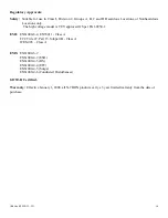
Page 14: ...e model is T V approved GS per EN 60950 1 EMI EN61000 6 4 EN55011 Class A FCC Title 47 Part 15 Subpart B Class A ICES 003 Class A EMS EN61000 6 2 EN61000 4 2 ESD EN61000 4 3 RS EN61000 4 4 EFT EN61000...

Page 15: ...RANTIES EXCLUSIVE IF AN N TRON PRODUCT DOES NOT OPERATE AS WARRANTED ABOVE CUSTOMER S SOLE REMEDY FOR BREACH OF THAT WARRANTY SHALL BE REPAIR REPLACEMENT OR REFUND OF THE PURCHASE PRICE PAID AT N TRON...

Reviews: