N.KO B10 ELECTRA Operation Manual Download Page 3


1.


General information


Thank you for purchasing one of our machines, and we hope that you will be fully satisfied.  


This guide provides instructions for the installation, adjustment, operation and 
maintenance of the machine B10 ELECTRA in compliance with valid safety standards. 


The information and data contained in this document subject to changes due to 
further improvement of machinery. To eliminate any doubts, when differences are 
detected, please contact N.KO Machines. 


Never  perform  any  operation  on  the  machine  before  you  read  the  instructions  in  the 
manual and understand them. Major part of accidents that happen in the workplace are 
due to the fact that the guidelines and recommendations contained in the manual are not 
complied with.  


The graphic symbols used in the manual are intended to emphasize the important 
information regarding the safety and operation of the machine. 


Attention :


Information important for the personal safety of the operating staff.


Important: 


Instruction that needs to be observed to ensure the proper function of the machine.
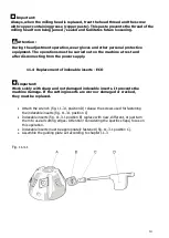


2.


Machine description B10 ELECTRA 


Machine B10 ELECTRA is designed solely for the activities below: 

B10 ELECTRA is designed solely for bevelling and fetch fettling of metal materials in the 
workshop or in the production hall. 
This includes manual and manually managed machine. The main feature of the machine 

is the ability to machine flat and shaped workpieces, openings, and tubes. The 

machining angle can be changed by replacing the milling head. B10 ELECTRA can 
perform also the workpiece edge rounding. This application also requires a special tool, 

see the text below. 

Use the machine in the environment protected from rain, snow, and other adverse 
weather conditions.  

Summary of Contents for B10 ELECTRA

Page 1: ...1 MANUAL BEVELLING AND DEBURRING SYSTEM B10 ELECTRA Ord no 25300 1 Phase 220V 25301 1 Phase 110V Operation manual for the device SUBJECT TO CHANGE...

Page 2: ...specifications 6 Accessories 7 Machine equipment 7 Control elements B10 ELECTRA 8 Use 9 Setting the removal size 9 Bevelling 11 Bevel angle and shape change 12 Milling head replacement 12 Replacement...

Page 3: ...s used in the manual are intended to emphasize the important information regarding the safety and operation of the machine Attention Information important for the personal safety of the operating staf...

Page 4: ...4 3 Identification data and CE Declaration of Conformity The identification data of machine B10 ELECTRA are listed on the label placed on the drive unit...

Page 5: ...potential warranty defects are removed free of charge and without undue delay so that the buyer is able to use the article the way they desire Should the buyer claim liability for warranty unrelated d...

Page 6: ...ine in humid environment and protect from high moisture Ensure good lighting at the workplace to prevent the risk of potential injury or eyesight damage Caution the tool milling machine is sharp with...

Page 7: ...dimensions 8 Machine equipment Unpack the machine from the cardboard box and check if the machine is ok and free from damage If necessary contact the seller Machine B10 ELECTRA is supplied with requir...

Page 8: ...or body C Scale for reading the bevel size setting D The miller unit with indexable inserts E Guiding stop miller roller and roller screw F The arresting screws of the thrust plate sleeve The set remo...

Page 9: ...F Turn the guiding plate fig 10 0 1 position G for setting the reduction size You can read the setting on the scale fig 10 0 1 position C The scale is just indikative The final result bevel size can...

Page 10: ...t when the miller touches the material edge for the first time This point can be set by gradual turning of the thrust plate fig 10 0 1 position G and placing to the material edge 45 For full bevel P 1...

Page 11: ...CAUTION The rebound is possible at this moment be careful Press the machine in the direction into the material until the miller is embedded in the material in the full profile of the set chip Contact...

Page 12: ...ig 11 3 1 position C Turn the guiding plate fig 11 3 1 position B for complete disassembly from the machine Secure the spindle against turning with the button which is located on the top side of the g...

Page 13: ...13 Fig 11 3 2 Fig 11 3 3 A B C...

Page 14: ...eplacement of indexable inserts ECO Important Work solely with sharp and not damaged indexable inserts It prevents the machine damage If the cutting inserts are worn or damaged or cracked they must be...

Page 15: ...fig 11 5 1 position C Turn the guiding plate fig 11 5 1 position B for complete disassembly from the machine Secure the spindle against turning with the button which is located on the top side of the...

Page 16: ...ure loosening Attention During the adjustment operation wear gloves and other personal protective equipment The operations must be carried out on the machine at rest and after disconnecting from the p...

Page 17: ...RA does not require any special tools and it is very simple Keep the machine clean and replace the lubrication grease in the machine gearbox every 1000 working hours This operation must be performed s...

Page 18: ...t be preserved greased Attention When using compressed air for cleaning wear safety goggles and never use a pressure exceeding 2 bar 13 Spare parts Orders of spare parts shall contain the following in...

Page 19: ...19...

Page 20: ...20...

Page 21: ...21...

Page 22: ...or s Address N KO spol s r o a Member of Richtr Group T borsk 398 22 293 01 Mlad Boleslav Czech Republic Europe Union Phone 420 326 772 001 fax 420 326 774 279 email nko nko cz USA Distributor s Addre...

Reviews: