background image

7

152 Push-to-open doors

883.101.11

GRYD Manual

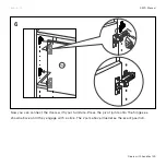
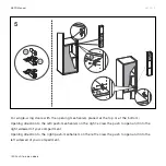
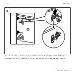
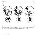
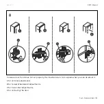
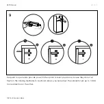
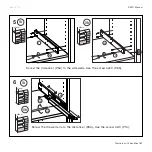
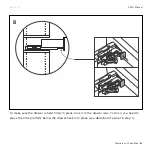
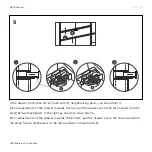
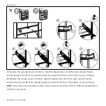
Now add the metal plate to the doors. The three illustrations above show which pre-drillings in 
the doors have to be used depending on the position of your opening mechanism.

Summary of Contents for GRYD

Page 1: ...GRYD ...

Page 2: ... 35 NORDYC Legs 51 SPYN Legs 67 Putting in Boards 83 Putting in Boards and Backwalls 95 Extensions 115 Extensions with backwalls 123 Doors with handles 131 Doors with push to open 143 Drawers with handles 155 Drawers with push to open 167 TABLE OF CONTENTS ...

Page 3: ...ure mounting only is as good as the connection between the mounting material dowels and the type of wall structure Unless you ordered an assembly service MYCS GmbH cannot judge the state of the wall structure The assembler assumes final responsibility for the dowels used Use only dowels suitable for that particular type of wall The appropriate dowels are available in any hardware store along with ...

Page 4: ...4 Introduction 883 101 00 GRYD Manual OUR MODULAR SYSTEM ...

Page 5: ...y made just for your product The manual explains how our system overall has to be assembled We know that this is a different approach Therefore we kindly ask you to read the following introductory pages carefully before starting the assembly process A lot of happy MYCS customers shared their feedback with us and often reported once the logic behind the system is clear assembling is an easy thing t...

Page 6: ...enwand aussen 41x47x2 cm Weiss 2 101 106 20 SU01 Seitenwand innen 41x47x2 cm Weiss 2 101 124 04 SU01 Schubladenbox Drucktürknopf 73x39x11 cm natur 5 801 101 01 Handling Charge 1 101 150 10 SU01 Rückwand 73x17cm Weiss 4er Pack 1 101 123 10 SU01 Schubladenfront 73x17x2 cm Weiss 4er Pack 1 101 150 00 SU01 Rückwand 73x17cm Weiss 2 101 140 20 SU01 Boden Top 73x47 cm Weiss 3 101 142 27 SU01 Boden Mitte ...

Page 7: ...from the bottom and then go from left to right First you assemble the leg construction if you ordered legs then you put the basic construction of sidewalls and boards together starting from the left and ending at the right This step can t be done alone since the construction gets it s stability afterwards from backwalls if ordered and the wall mounting Once this is done the construction should be ...

Page 8: ...2 5 6 1 3 4 8 Introduction 883 101 00 GRYD Manual ...

Page 9: ...t with the left bottom board and end with the top board on the very right Wall mounting Your furniture is getting bigger Please level it now and then connect the furniture to the wall Please note that the mounting material provided in the accessory box is mainly a safety feature and not suitable for hanging your furniture on the wall Extensions Due to stability reasons our sidewalls come in one pi...

Page 10: ...com ww w m ycs co m 10 Introduction 883 101 00 GRYD Manual DON T FORGET TO MEASURE To help you find the correct spot to place your boards we added a small measure to the back of this manual Please use it as a reference as shown in the illustration above drawer door ...

Page 11: ...nd aussen 41x47x2 cm Weiss 2 101 106 20 SU01 Seitenwand innen 41x47x2 cm Weiss 2 101 124 04 SU01 Schubladenbox Drucktürknopf 73x39x11 cm natur 5 801 101 01 Handling Charge 1 101 150 10 SU01 Rückwand 73x17cm Weiss 4er Pack 1 101 123 10 SU01 Schubladenfront 73x17x2 cm Weiss 4er Pack 1 101 150 00 SU01 Rückwand 73x17cm Weiss 2 101 140 20 SU01 Boden Top 73x47 cm Weiss 3 101 142 27 SU01 Boden Mitte 73x4...

Page 12: ...out where to place the shelf boards At MYCS the customer designs the product The boards should be placed according to your own design You received a print out of your product alongside the accessories Please use the print out to locate the correct board position Please note if your product includes backwalls it is no longer possible to reposition them as they match your own design exactly I ordere...

Page 13: ...using screw 10014 P49 the surface should stay intact Why are there tiny holes in the middle of the shelf boards The four small holes on the bottom of longer boards are there for push to open accessory housing to be installed if your design includes double doors The product is not stable enough and is falling over during the time of assembly As written in our manual please always perform the assemb...

Page 14: ... or restrainig straps delivered along with the furniture except for furniture equipped with SPYN legs Please note brackets and straps are safety features only Also they help to stabilise your furniture but have no load bearing function Our handles have edges that may be sharp and pointy For toddlers and small children safety we recommend a securing edges and corners with appropriate protection of ...

Page 15: ...You will build something similar to this CLASSYC LEGS FOR GRYD ...

Page 16: ...101 108 208 xx 101 109 209 xx 101 110 210 xx 101 111 211 xx 902 100 19 902 100 34 902 100 25 901 300 01 901 300 02 101 168 268 xx 101 170 00 101 169 xx 883 101 01 GRYD Manual CLASSYC Legs Outer Sidewalls Inner Sidewalls Here are the parts you will need Square felt pad Hex Key Size 4 Hex Key Size 6 CLASSYC Leg CLASSYC Support Leg CLASSYC Leg Metal Screw 6 x 35mm Screw 6 x 20mm ...

Page 17: ...ult Since you ordered another type of leg you don t need them for your furniture Please remove all of them as shown above Depending on your configuration screw Classyc metal leg P27 illustration on the left or Classyc square leg P33 illustration on the right into both outer sidewalls as seen above ...

Page 18: ...1 01 GRYD Manual CLASSYC Legs Connect support leg P28 with all inner sidewalls as seen above using screw P30 Add paddings under the leg construction as shown above The paddings will protect your floor from scratches ...

Page 19: ...CYRCLE LEGS FOR GRYD You will build something similar to this ...

Page 20: ...LE Legs 883 101 02 GRYD Manual Here are the parts you will need x2 for each end of the platform x1 or more depending on your configuration x1 or more depending on your configuration x1 or more depending on your configuration Leg Platform Plate Single sided Leg Platform Plate Double sided Platform Profile 37cm Platform Profile 73cm CYRCLE Legs Flat head screw 8 x 14mm Screw distancer Truss screw 3 ...

Page 21: ...0 xx 101 101 201 xx 101 102 202 xx 101 103 203 xx 101 104 204 xx 101 105 205 xx 101 106 206 xx 101 107 207 xx 101 108 208 xx 101 109 209 xx 101 110 210 xx 101 111 211 xx CYRCLE Legs 883 101 02 GRYD Manual Bottom Board Metal shelf support Screw Varianta 3 x 10mm Outer Sidewalls Inner Sidewalls ...

Page 22: ...connect with the CYRCLE leg The double platform s belong below the inner sidewall s and connect with the support leg that is needed for stability reasons NOTE you need to add one support leg per inner sidewall If you assemble one or more inner sidewalls without a support leg stability can t be guaranteed ...

Page 23: ...nual Have a look at the example constructions on the left and how the leg construction for these examples look like on the right Find the one construction that matches your design the best and assemble the leg construction accordingly ...

Page 24: ...are installation of CYRCLE leg below outer sidewall connect single end platform P2 and two profiles of P3 or P4 depending on configuration with the screw P7 Pay attention to illustration left make sure to connect the platform from the right side ...

Page 25: ...epare installation of support leg below inner sidewall connect double platform P1 and two profiles of P3 or P4 depending on configuration with the screw P7 Pay attention to illustration left make sure to connect the platform from the right side ...

Page 26: ...es of the product pos E or D if it is tall 130cm or more or expected to hold a lot of weight NOTE Repeat step for all CYRCLE legs based on your configuration Screw support leg P6 into the platform P1 As you can see on the right you have two options NOTE The support leg needs to be installed at the back of the actual product not at the front NOTE Repeat step for all support legs total number depend...

Page 27: ...atches stick the paddings P9 to CYRCLE P23 and support leg P6 Place the leg construction at the target location of your furniture Pay attention to the location of the support leg at the back not at the front NOTE Pay attention to the position of the hinge as illustrated in A above ...

Page 28: ...g the support leg s as shown above This step is particularly important as it prevents the construction from bending All our sidewalls come with smaller metal legs by default Since you ordered another type of leg you don t need them for your furniture Please remove all of them as shown above ...

Page 29: ...to all sidewalls as shown above using screw P14 Please check your configuration to figure out where to screw in the support You need to use them wherever you placed a board Please refer to the Don t forget to measure tip from the Introduction chapter on page 10 for details on how to position the metal shelf supports correctly ...

Page 30: ...10 30 CYRCLE Legs 883 101 02 GRYD Manual Screw in distancer P11 and pad P10 to the bottom boards P25 by using the screw P12 3 5 x 25mm ...

Page 31: ...E Legs 883 101 02 GRYD Manual Now stick the first two sidewalls into their platform the outer sidewalls go into the end of the single end platform P2 and the inner sidewall in the middle of the double platform P1 ...

Page 32: ...12 32 CYRCLE Legs 883 101 02 GRYD Manual Place bottom boards P25 on the platform by joining it to the sidewalls P34 P35 with additional help ...

Page 33: ... 101 02 GRYD Manual Screw in the sidewalls P34 P35 to the bottom boards and turn the lock underneath the bottom board to connect the rails with the board You should hear a click sound once the lock is in its final position ...

Page 34: ...he number of sidewalls you have ordered Please connect two sidewalls on the left side of your product with their platform step 11 mount the bottom board in the middle of them step 12 and finally lock the bottom platform with the rails step 13 Repeat steps 11 to 13 by adding sidewalls one at a time until you reach the outer sidewall on the right hand side of your product ...

Page 35: ...LYFT LEGS FOR GRYD You will build something similar to this ...

Page 36: ...e are the parts you will need x2 for each end of the platform x1 or more depending on your configuration x1 or more depending on your configuration x1 or more depending on your configuration Leg Platform Plate Single sided Leg Platform Plate Double sided Platform Profile 37cm Platform Profile 73cm Flat head screw 8 x 14mm Pan head screw 6 x 16mm Round felt pad Screw distancer Truss screw 3 5 x 25m...

Page 37: ... xx 101 110 210 xx 101 111 211 xx 101 161 261 xx 101 163 263 xx 101 162 262 xx 101 164 264 xx 902 100 19 101 160 260 xx 902 100 23 902 100 24 101 171 271 xx 101 172 272 xx LYFT Legs GRYD Manual 883 101 03 Outer Sidewalls Inner Sidewalls Interior socle 73cm Exterior socle 37cm Socle attachment Exterior socle 73cm Interior socle 37cm Flat head screw 6 x 65mm Square felt pad Truss screw 4 5 x 45mm Bo...

Page 38: ...P34 P35 P34 P25 P25 38 LYFT Legs 883 101 03 GRYD Manual Overall the single platforms belong below the outer sidewalls and the double platform s belong below the inner sidewall s ...

Page 39: ...01 03 Have a look at the example constructions on the left and what the leg construction for these examples look like on the right Find the construction that matches your design the best and assemble the leg construction accordingly ...

Page 40: ...3 GRYD Manual Prepare installation of LYFT leg below outer sidewall connect single end platform P2 and two profiles of P3 or P4 depending on configuration with the screw P7 Pay attention to the illustration left make sure to connect the platform from the right side ...

Page 41: ... GRYD Manual 883 101 03 Prepare installation below inner sidewall connect double platform P1 and two profiles of P3 or P4 depending on configuration with the screw P7 Pay attention to illustration left make sure to connect the platform from the right side ...

Page 42: ...ment P19 with your socles P17 P18 depending on configuration using screw P22 If your product only has two sidewalls If your furniture does not have more than two sidewalls connect socle construction with single end platform P2 as seen above using screw P21 Make sure to match position of hinge as seen in A on the right side ...

Page 43: ... than two sidewalls If your furniture has more than two sidewalls connect socle construction with platforms using screw P21 as seen on the illustration above Add paddings under the socle construction as seen above The paddings will protect your floor from scratches ...

Page 44: ...3 101 03 GRYD Manual Remove front panel from socle construction needed for step 14 Place the leg construction at the target location of your furniture Make sure to place the open socle part at the front of your furniture ...

Page 45: ...ve The metal shelf supports P13 are there to hold the bottom boards Screw the supports into all sidewalls as shown above using screw P14 Please check your configuration to figure out where to screw in the support You need to use them wherever you placed a board Please refer to the Don t forget to measure tip from the Introduction chapter on page 10 for details on how to position the metal shelf su...

Page 46: ...11 46 LYFT Legs 883 101 03 GRYD Manual Screw in distancer P11 and pad P10 to the bottom boards P25 by using the screw P12 3 5 x 25mm ...

Page 47: ... Legs GRYD Manual 883 101 03 Now stick the first two sidewalls into their platform The outer sidewalls go into the end of the single end platform P2 and the inner sidewall in the middle of the double platform P1 ...

Page 48: ...13 48 LYFT Legs 883 101 03 GRYD Manual Place bottom boards P25 on the platform by joining it to the sidewalls P26 with additional help ...

Page 49: ...the hinge underneath the bottom board to connect the rails with the board You should hear a click sound once the lock is in its final position 2 Once this is done put the front part s of the socle back into place as they have been removed in step 7 ...

Page 50: ...3 15 LYFT Legs 883 101 03 GRYD Manual NOTE Step 12 to 14 go together and have to be performed multiple times if your configuration requires it depending on the number of sidewalls you have ordered Please connect two sidewalls on the left hand side of your product with their platform step 12 mount the bottom board in the middle of them step 13 and finally lock the bottom platform with the rails ste...

Page 51: ...NORDYC LEGS FOR GRYD You will build something similar to this ...

Page 52: ...YC Legs 883 101 04 GRYD Manual Here are the parts you will need NORDYC Legs x2 for each end of the platform x1 or more depending on your configuration x1 or more depending on your configuration x1 or more depending on your configuration Leg Platform Plate Single sided Leg Platform Plate Double sided Platform Profile 37cm Platform Profile 73cm Support Leg Flat head screw 8 x 14mm Pan head screw 6 x...

Page 53: ...0 xx 101 101 201 xx 101 102 202 xx 101 103 203 xx 101 104 204 xx 101 105 205 xx 101 106 206 xx 101 107 207 xx 101 108 208 xx 101 109 209 xx 101 110 210 xx 101 111 211 xx NORDYC Legs 883 101 04 GRYD Manual Metal shelf support Screw Varianta 3 x 10mm Bottom Board Outer Sidewalls Inner Sidewalls ...

Page 54: ...walls and connect with the NORDYC leg The double platform s belong below the inner sidewall s and connect with the support leg that is needed for stability reasons NOTE you need to add one support leg per inner sidewall If you assemble one or more inner sidewalls without a support leg stability can t be guaranteed ...

Page 55: ...anual Have a look at the example constructions on the left and what the leg construction for these examples looks like on the right Find the construction that matches your design the best and assemble the leg construction accordingly ...

Page 56: ...04 GRYD Manual Prepare installment of NORDYC leg below outer sidewall connect single end platform P2 and two profiles of P3 or P4 depending on configuration with the screw P7 Pay attention to the illustration left make sure to connect the platform from the right side ...

Page 57: ...01 04 GRYD Manual Prepare installment of support leg below inner sidewall connect double platform P1 and two profiles of P3 or P4 depending on configuration with the screw P7 Pay attention to illustration left make sure to connect the platform from the right side ...

Page 58: ...rnal edges of the product pos D if it is tall 130cm or more or expected to hold a lot of weight NOTE Repeat step for all NORDYC legs based on your configuration Screw support leg P6 into the platform P1 As you can see on the right you have two options NOTE The support leg needs to be installed at the back of the actual product not at the front NOTE Repeat step for all support legs total number dep...

Page 59: ...m scratches stick the paddings P9 to NORDYC P5 and support leg P6 Place the leg construction at the target location of your furniture Pay attention to the location of the support leg at the back not at the front NOTE Pay attention to the position of the hinge as illustrated in A on the right ...

Page 60: ...ng the support leg s as shown above This step is particularly important as it prevents the construction from bending All our sidewalls come with smaller metal legs by default As you ordered another type of leg you don t need them for your furniture Please remove all of them as shown above ...

Page 61: ... supports into all sidewalls as shown above using screw P14 Please check your configuration to figure out where to screw in the support You need to use them wherever you placed a board Please refer to the Don t forget to measure tip from the Introduction chapter on page 10 for details on how to position the metal shelf supports correctly ...

Page 62: ...10 62 NORDYC Legs 883 101 04 GRYD Manual Screw in distancer P11 and pad P10 to the bottom boards P25 by using the screw P12 3 5 x 25mm ...

Page 63: ... NORDYC Legs 883 101 04 GRYD Manual Now stick the first two sidewalls into their platform the outer sidewalls go into the end of the single end platform P2 and the inner sidewall in the middle of the double platform P1 ...

Page 64: ...12 64 NORDYC Legs 883 101 04 GRYD Manual Place bottom boards P25 on the platform by joining it to the sidewalls P34 P35 with additional help ...

Page 65: ... 883 101 04 GRYD Manual Screw in the sidewalls to the bottom boards and turn the lock underneath the bottom board to connect the rails with the board You should hear a click sound once the lock is in its final position ...

Page 66: ... number of sidewalls you have ordered Please connect two sidewalls on the left hand side of your product with their platform step 11 mount the bottom board in the middle of them step 12 and finally lock the bottom platform with the rails step 13 Repeat steps 11 to 13 by adding one sidewall at a time until you reach the outer sidewall on the right hand side of your product ...

Page 67: ...SPYN LEGS FOR GRYD You will build something similar to this ...

Page 68: ... Here are the parts you will need x2 for each end of the platform x1 or more depending on your configuration x1 or more depending on your configuration x1 or more depending on your configuration Leg Platform Plate Single sided Leg Platform Plate Double sided Platform Profile 37cm Platform Profile 73cm Flat head screw 8 x 14mm SPYN Legs Metal shelf support Screw Varianta 3 x 10mm Screw distancer Tr...

Page 69: ...00 200 xx 101 101 201 xx 101 102 202 xx 101 103 203 xx 101 104 204 xx 101 105 205 xx 101 106 206 xx 101 107 207 xx 101 108 208 xx 101 109 209 xx 101 110 210 xx 101 111 211 xx SPYN Legs 883 101 05 GRYD Manual Bottom Board Outer Sidewalls Inner Sidewalls ...

Page 70: ...latform s belong below the inner sidewall s NOTE the maximum carrying capacity per wheel is 50kg E g the maximum weight of a GRYD SPYN construction with 4 wheels is 200kg Please calculate the maximum capacity of your furniture accordingly number of wheel 50kg and keep it in mind once you add your personal belongings to your furniture ...

Page 71: ...ual Have a look at the example constructions on the left and what the leg construction for their examples look like on the right Find the one construction that matches your design the best and assemble the leg construction accordingly ...

Page 72: ...re installment of Spyn leg below outer sidewall connect single end platform P2 and two profiles of P3 or P4 depending on configuration with the screw P7 Pay attention to the illustration left make sure to connect the platform from the right side ...

Page 73: ...are installation of Spyn leg below inner sidewall connect double platform P1 and two profiles of P3 or P4 depending on configuration with the screw P7 Pay attention to the illustration left make sure to connect the platform from the right side ...

Page 74: ...nual 1 Remove connector screw from wheel s 2 Screw in connector screw into single end platform P2 double platform P1 as seen above 3 Plug wheel into connector screw You should hear a click sound once the wheel is in its final position ...

Page 75: ...ion of the hinges as seen in A above Otherwise you won t be able to mount the sidewalls properly All our sidewalls come with smaller metal legs by default As you ordered another type of leg you don t need them for your furniture Please remove all of them as shown above ...

Page 76: ...o all sidewalls as shown above using screw P14 Please check your configuration to figure out where to screw in the support You need to use them wherever you placed a board Please refer to the Don t forget to measure tip from the Introduction chapter on page 10 for details on how to position the metal shelf supports correctly ...

Page 77: ...77 SPYN Legs 883 101 05 GRYD Manual Now prepare the bottom boards to be connected with the existing construction Screw in distancer P11 and pad P10 to the bottom boards P25 by using the screw P12 3 5x25mm ...

Page 78: ... Legs 883 101 05 GRYD Manual Now stick the first two sidewalls into their platform The outer sidewalls go into the end of the single end platform P2 and the inner sidewall in the middle of the double platform P1 ...

Page 79: ...9 79 SPYN Legs 883 101 05 GRYD Manual Place bottom boards P25 on the platform by joining it to the sidewalls P34 P35 with additional help ...

Page 80: ... 05 GRYD Manual Screw in the sidewalls P34 P35 to the bottom boards and turn the hinge lock underneath the bottom board to connect the rails with the board You should hear a click sound once the lock is in its final position ...

Page 81: ...e number of sidewalls you have ordered Please connect two sidewalls on the left hand side of your product with their platform step 8 mount the bottom board in the middle of them step 10 and finally lock the bottom platform with the rails step 10 Repeat steps 8 to 10 by adding one sidewall at a time until you reach the outer sidewall on the right hand side of your product ...

Page 82: ... two sidewalls and their connecting boards needs at least one backwall to guarantee stability Installing backwalls will be covered in the following pages NOTE please do not attach your furniture to the wall nor level it as explained in step 3 and 9 11 in the following pages ...

Page 83: ...PUTTING IN BOARDS FOR GRYD You will build something similar to this ...

Page 84: ... xx 101 105 205 xx 101 114 214 xx 101 118 218 xx 101 106 206 xx 101 107 207 xx 101 108 208 xx 101 109 209 xx 101 110 210 xx 101 111 211 xx 101 112 212 xx 101 116 216 xx Putting in Boards 883 101 07 GRYD Manual Here are the parts you will need Metal shelf support Metal bracket set Screw Varianta 3 x 10mm Hexagonal wrench Outer Sidewalls Door board Inner Sidewalls Board ...

Page 85: ...y during assembly We highly recommend checking the final measurements of your furniture now and to build your furniture directly at the desired final location Make sure to measure the space of the final location of your furniture and leave enough room to move around comfortably during assembly ...

Page 86: ...These are there to hold the boards You ll need them in the last holes to hold the bottom boards Please check your configuration to figure out where to screw in the support You need to use them wherever you placed a board Please refer to the Don t forget to measure tip from the Introduction chapter on page 10 for details on how to position the metal shelf supports correctly ...

Page 87: ...oard P43 They all come with four connecting sockets that match the metal shelf supports you added in the previous step Make sure to connect the board from the correct side and in the correct direction Please see the illustration above for more details of what to watch out for ...

Page 88: ...4 88 Putting in Boards 883 101 07 GRYD Manual Keep on adding boards according to your design and tie them up as seen above NOTE Do not add the top board yet This will be added later on ...

Page 89: ...ok at your furniture design and repeat steps two to seven as often as needed by adding sidewall by sidewall and connect them with bottom and middle boards Move from left to right Once you reach the right hand side of your furniture move on to the next pages NOTE Please always skip the top board This one is to be added a little later ...

Page 90: ...need to make sure everything is levelled To help you out with this our sidewalls come with 3 metal legs by default The maximum adjustable height is 15mm Use the key P37 to adjust the height wherever needed to level your furniture NOTE Do not skip this step As the next step will involve attaching your furniture to the wall you need to do the levelling now ...

Page 91: ...o matter what size your product is use at least two brackets Place the brackets below the boards up to eye level and above the boards above eye level simply to avoid them being seen from a distance From the eight simple product examples above pick the one that is matches your construction best and use the frequency and placement of wall mountings for your product ...

Page 92: ...n above with the metal bracket provided P42 Leave about 10cm space at the top of the sidewall Repeat this step according to the explanation on the previous page NOTE The provided metal bracket is a safety feature Also it helps to stabilise your furniture but it has no load bearing function ...

Page 93: ...e a different size but have to be installed in exactly the same way as the normal boards Please check your design and place the door boards where they belong Once the brackets are all in place you can move on and add the final top boards Proceed as in the steps before and pay attention to the direction of the top board as illustrated above ...

Page 94: ...11 94 Putting in Boards 883 101 07 GRYD Manual Repeat the previous steps as many times as you need to reach the top right of your furniture ...

Page 95: ...PUTTING IN BOARDS AND BACKWALLS FOR GRYD You will build something similar to this ...

Page 96: ...201 xx 101 102 202 xx 101 103 203 xx 101 104 204 xx 101 105 205 xx 101 106 206 xx 101 107 207 xx 101 108 208 xx 101 109 209 xx 101 110 210 xx 101 111 211 xx 901 100 06 901 100 17 901 100 37 101 148 248 xx 101 149 249 xx Putting in Boards and Backwalls 883 101 06 GRYD Manual Metal shelf support Screw Varianta 3 x 10mm Hexagonal wrench Outer Sidewalls Inner Sidewalls Middle and bottom board Middle a...

Page 97: ...ht very quickly during assembly We highly recommend checking the final measurements of your furniture now and to build it directly at the desired final location Make sure to measure the space of the final location of your furniture and leave enough room to move around comfortably during assembly ...

Page 98: ... above These are there to hold the boards You ll need them in the last holes to hold the bottom boards Please check your configuration to figure out where to screw in the support You need to use them wherever you placed a board Please refer to the Don t forget to measure tip from the Introduction chapter on page 10 for details on how to position the metal shelf supports correctly ...

Page 99: ...ture with your wall and prevents the furniture from tipping over To attach the strap to your sidewall you need to drill a small hole Ø 2 5mm and 10mm deep into your sidewall There is no fixed spot where you should drill the hole but we recommend leaving about 10 cm space at the top of the sidewall The tip over restraint only works properly if it is placed towards the top section of your product ...

Page 100: ...with four connecting sockets that match the metal shelf supports you added in step 2 Make sure to connect the board from the correct side and in a way that the restraining strap you added in the last step is at the back of your furniture Please see the illustration above for more details of what to watch out for ...

Page 101: ... Once the bottom board is in place you can add a backwall P41 All our backwalls come with a plug in connector and fit exactly into the pre drilled holes of the boards NOTE Once a backwall is installed you won t be able to change the position of the board anymore ...

Page 102: ...45 102 101 120 220 XX 101 131 231 XX 101 121 221 XX 101 132 232 XX 101 133 233 XX 101 134 234 XX 101 135 235 XX Putting in Boards and Backwalls 883 101 06 GRYD Manual BOARD BEHIND FRONTS 36 74 cm BOARD BETWEEN FRONTS DIVIDING BACKWALLS BOARD BEHIND FRONTS 55 113 151 190 228 cm DIVIDING BACKWALLS ...

Page 103: ...existing construction the board will fit into the plug in connector of the backwall and into the metal shelf supports of the sidewalls Keep on adding boards and backwalls according to your design and tie up the boards as seen above on the right NOTE Do not add the last backwall and the top board yet These ones follow later on ...

Page 104: ...ctor of the backwall and into the metal shelf supports of the sidewalls Keep on adding boards and backwalls according to your design and tie up the boards as seen above on the right NOTE Do not add the last backwall and the top board yet These ones follow later on P45 P45 104 Putting in Boards and Backwalls 883 101 06 GRYD Manual ...

Page 105: ...urniture design and repeat steps two to seven as often as needed by adding sidewall by sidewall and connect them with bottom middle boards and the corresponding backwalls Move from left to right Once you reach the right hand end of your furniture move on to the next pages NOTE Please always skip the top backwall and board These are to be added a little later ...

Page 106: ...ll you need to make sure everything is levelled To help you out with this our sidewalls come with 3 metal legs by default The maximum adjustable height is 15 mm Use the key P37 to adjust the height wherever needed to level your furniture NOTE Do not skip this step As the next step will involve attaching your furniture to the wall you need to do the levelling now ...

Page 107: ...sign NOTE No matter what size your product is use at least two straps Place the straps below the boards up to eye level and above the boards above eye level simply to avoid them being seen from a distance From the eight simple product examples above pick the one that matches your construction best and use the frequency and placement of wall mountings for your product ...

Page 108: ...l as shown above Please make sure to create a right angle 90 with the strap as shown in 2 above Repeat this step according to the explanation on the previous page NOTE The restraining strap provided is a safety feature Also it helps to stabilise your furniture but it has no load bearing function ...

Page 109: ... Once the straps are all in place you can move on and add the final backwalls and top boards Proceed as in the steps before and pay attention to the direction of the top board as illustrated above NOTE If your furniture is taller than 233cm please skip this step ...

Page 110: ...GRYD Manual If you placed a board behind a door in your furniture design The door boards P40 are a different size but have to be installed in exactly the same way as the normal boards Please check your design and place the door boards where they belong ...

Page 111: ...14 111 Putting in Boards and Backwalls 883 101 06 GRYD Manual Repeat the previous steps as many times as you need to reach the top right of your furniture ...

Page 112: ... and Backwalls 883 101 06 GRYD Manual NOTE If your configuration has sections without backwalls we suggest an additional fix to the wall with the provided angles P42 Please follow the rules from step 10 to place them correctly ...

Page 113: ...113 Putting in Boards and Backwalls 883 101 06 GRYD Manual ...

Page 114: ...114 Putting in Boards and Backwalls 883 101 06 GRYD Manual ...

Page 115: ...EXTENSIONS FOR GRYD You will build something similar to this ...

Page 116: ... 101 106 206 xx 101 107 207 xx 101 108 208 xx 101 109 209 xx 101 110 210 xx 101 111 211 xx 901 100 04 901 100 17 901 100 37 901 100 05 901 100 19 101 112 212 xx 101 116 216 xx Extensions 883 101 09 GRYD Manual Here are the parts you will need Outer extensions Inner extensions Wooden dowel 8 x 30mm Outer Sidewalls Inner Sidewalls Metal shelf support Metal bracket set Screw Varianta 3 x 10mm Board ...

Page 117: ...9 GRYD Manual Add metal shelf supports P13 to the extension sidewalls according to the location of the boards check your configuration if you re unsure Pay attention to reference A in order to mount the extension walls from the correct side ...

Page 118: ...ewalls with your existing construction Use the dowels P46 for this step NOTE Once again make sure to connect the extension from the correct side The illustration on the right explains how you can use the ruler printed on the back of this manual to check whether or not you are connecting it from the correct side ...

Page 119: ...e wall as shown above with the metal bracket provided P42 Leave around about 5cm space at the top of the sidewall Repeat this step accordingly NOTE The metal bracket provided is a safety feature only Also it helps to stabilise your furniture but it has no load bearing function ...

Page 120: ...ce the brackets are all in place you can move on and add further boards and finally the top board according to your configuration Proceed as in the steps before and make sure to fix the boards with the metal shelf supports as illustrated above on the right ...

Page 121: ... your furniture design and repeat steps one to four as often as needed by adding one extension wall at a time and connect them with middle and top boards Move from left to right Once you reach the right hand end of your furniture move on to the next pages ...

Page 122: ......

Page 123: ...EXTENSIONS WITH BACKWALLS FOR GRYD You will build something similar to this ...

Page 124: ... 111 211 xx 901 100 04 901 100 05 901 100 19 901 100 06 101 150 250 xx 101 151 251 xx 101 152 252 xx 101 153 253 xx 101 154 254 xx 101 155 255 xx 101 140 240 xx 101 144 244 xx 101 142 242 xx 101 146 246 xx Extensions with backwalls 883 101 08 GRYD Manual Here are the parts you will need Outer extensions Inner extensions Wooden dowel 8 x 30mm Outer Sidewalls Inner Sidewalls Metal shelf support Scre...

Page 125: ...3 101 08 GRYD Manual Add metal shelf supports P13 to the extension sidewalls according to the location of the boards check your configuration if you re unsure Pay attention to reference A in order to mount the extension walls from the correct side ...

Page 126: ...ur wall and prevents the furniture from tipping over To attach the strap to your sidewall you need to drill a small hole Ø 2 5mm and 10mm deep into your sidewall There is no fixed spot where you should place the drilling but we recommend leaving about 5cm space at the top of the sidewall NOTE Adding the tip over restraint can t be skipped and is important to stabilize your product ...

Page 127: ...ion sidewalls with your existing construction Use the dowels P46 for this step NOTE Once again make sure to connect the extension from the correct side The illustration on the right explains how you can use the ruler printed on the back of this manual to check whether or not you are connecting it from the correct side ...

Page 128: ...wn above Plesae make sure to create a right angle 90 with the strap as shown in 2 above Repeat this step accordingly repeating logic explained in manual 7 8 step 11 NOTE The restraining strap provided is a safety feature Also it helps to stabilise your furniture but it has no load bearing function ...

Page 129: ... GRYD Manual Once the straps are all in place you can move on and add further backwalls and boards according to your configuration Proceed as in the steps before and make sure to fix the board with the metal shelf supports as illustrated above on the right ...

Page 130: ...te the assembly for this compartment Have a look at your furniture design and repeat steps one to six as often as needed by adding one extension wall at a time and connect them with middle and top boards Move from left to right Once you reach the right hand side of your furniture move on to the next pages ...

Page 131: ...DOORS WITH HANDLES FOR GRYD You will build something similar to this ...

Page 132: ...01 100 20 901 100 01 101 175 0x 101 124 12 901 101 07 901 101 08 Doors with handles 883 101 10 GRYD Manual Here are the parts you will need Soft close mechanism Screw US 3 5 x 13mm Screw US 3 x 13mm Adapter with regulation Door handle Screw Varianta 3 x 10mm Mounting plate for hinges Hinge soft close ...

Page 133: ... cm 151 cm 190 cm 228 cm x2 x2 I x2 x2 x2 x3 II x2 x2 x4 III I II III 133 101 120 220 XX 101 131 231 XX 101 121 221 XX 101 132 232 XX 101 133 233 XX 101 134 234 XX 101 135 235 XX Doors with handles 883 101 10 GRYD Manual Doors ...

Page 134: ...ght It s up to you Our recommendation Place the opening mechanism at the top area of each door from the bottom of your product up to eye level Above eye level place the mechanism at the bottom area of the door This makes it easier if you want to open it later on For single wing doors make sure the doors on the left half of your product open to the left and the ones on the right part open to the ri...

Page 135: ...2 P47 135 Doors with handles 883 101 10 GRYD Manual All our doors come flat packed to minimise packaging space To install the doors you need to prepare them by screwing in the pivot joints first ...

Page 136: ...ng direction to the left screw in the hinges into the left sidewall of the compartment Leave a distance of one hole from the bottom and one hole from the top board of the compartment Opening direction to the right screw in the hinges into the right sidewall of your compartment Leave a distance of one hole from the bottom and one hole from the top board of the compartment ...

Page 137: ...ep we show you how to install it At first you need to connect the two elements that belong to the magnetic closing unit P51 P53 and screw it into the pre drillings You need to do this twice once for the left door and once for the door on the right The pre drillings can be found in the middle board that is supposed to be the top of the compartment the doors are supposed to close ...

Page 138: ... placed at the top or at the bottom Opening direction to the left handle on the right screw the magnetic closing unit into the right sidewall of your compartment Opening direction to the right handle on the left screw the magnetic closing unit into the left sidewall of your compartment ...

Page 139: ...ith handles 883 101 10 GRYD Manual Now you can connect the doors with your furniture Press the pivot joints onto the hinges as shown above until they engage with a click The zoom above illustrates the exact position ...

Page 140: ... 228 cm x2 x2 x2 x1 x2 x1 x2 x1 110 cm 140 101 120 220 XX 101 131 231 XX 101 121 221 XX 101 132 232 XX 101 133 233 XX 101 134 234 XX 101 135 235 XX Doors with handles 883 101 10 GRYD Manual Screw in the handles at the position of your choice ...

Page 141: ...th handles 883 101 10 GRYD Manual In case a door front does not sit properly this is what you can do A for vertical adjustments B for forward backward adjustments C for horizontal adjustments D for removing the door ...

Page 142: ...10 GRYD Manual Our magnetic closing units provide you with the option to level your doors in case they do not sit flush on the closing mechanism As shown above you can adjust the connector pin up to 1 5mm in one direction or the other ...

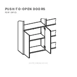
Page 143: ...PUSH TO OPEN DOORS FOR GRYD You will build something similar to this ...

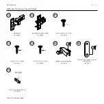
Page 144: ...4 901 100 20 901 100 01 101 124 02 901 100 02 Push to open doors 883 101 11 GRYD Manual Here are the parts you will need Screw Varianta 3 x 10mm Mounting plate for hinges Hinge push Screw US 3 5 x 13mm Screw US 3 0 x 13mm Adapter with regulation Metal plate for push to open mechanism Push to open mechanism BLACK ...

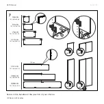
Page 145: ... cm 151 cm 190 cm 228 cm x2 x2 I x2 x2 x2 x3 II x2 x2 x4 III I II III 145 101 120 220 XX 101 131 231 XX 101 121 221 XX 101 132 232 XX 101 133 233 XX 101 134 234 XX 101 135 235 XX Push to open doors 883 101 11 GRYD Manual Doors ...

Page 146: ...ght It s up to you Our recommendation Place the opening mechanism at the top area of each door from the bottom of your product up to eye level Above eye level place the mechanism at the bottom area of the door This makes it easier if you want to open it later on For single wing doors make sure the doors on the left half of your product open to the left and the ones on the right part open to the ri...

Page 147: ...2 147 Push to open doors 883 101 11 GRYD Manual All our doors come flat packed to minimise packaging space To install the doors you need to prepare them by screwing in the pivot joints first ...

Page 148: ...ning direction to the left screw in the hinges into the left sidewall of the compartment Leave a distance of one hole from the bottom and one hole from the top board of the compartment Opening direction to the right screw in the hinges into the right sidewall of your compartment Leave a distance of one hole from the bottom and one hole from the top board of the compartment ...

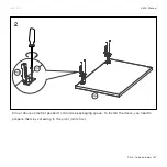
Page 149: ...wo elements that belong to the push to open unit P51 P58 and screw it into the pre drillings You need to do this twice once for the left door and once for the door on the right The pre drillings can be found in the middle board that is supposed to be the top of the compartment that is closed by the doors ...

Page 150: ...sm placed at the top or at the bottom Opening direction to the left push mechanism on the right screw the push to open unit into the right sidewall of your compartment Opening direction to the right push mechanism on the left screw the push to open unit into the left sidewall of your compartment ...

Page 151: ... open doors 883 101 11 GRYD Manual Now you can connect the doors with your furniture Press the pivot joints onto the hinges as shown above until they engage with a click The zoom above illustrates the exact position ...

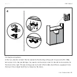
Page 152: ...h to open doors 883 101 11 GRYD Manual Now add the metal plate to the doors The three illustrations above show which pre drillings in the doors have to be used depending on the position of your opening mechanism ...

Page 153: ...1 11 GRYD Manual In case a door front does not sit properly the illustrations A to D explain what you can do about it A for vertical adjustments B for forward backward adjustments C for horizontal adjustments D for removing the door ...

Page 154: ...1 11 GRYD Manual Our push to open units provide you with the option to level your doors in case they do not sit flush on the closing mechanism As shown above you can adjust the connector pin up to 1 5mm in one direction or the other ...

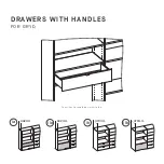
Page 155: ...342mm 470mm 470mm 342mm Ia IIa Ib IIb DRAWERS WITH HANDLES FOR GRYD You will build something similar to this ...

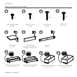
Page 156: ...x 101 137 237 xx 101 124 10 101 124 11 101 124 13 101 124 14 101 124 15 101 124 16 101 124 17 101 124 18 Drawers with handles 883 101 12 GRYD Manual Here are the parts you will need Drawer Frontplate Drawer Box 34cm deep shelf Drawer Box 47cm deep shelf Screw US 3 x 13mm Screw 4 x 25mm Screw Varianta 3 x 10mm Door handle Screw 4 x 20mm Distancer High Drawer Box 34cm deep High Drawer Box 47cm deep ...

Page 157: ...tegrate them with your furniture you have to separate the pieces first 1 Pull the little platform within the fixture construction at the bottom of the drawer as illustrated above 2 Hold the rails and carefully lift the drawer box 3 Pull the drawer box out 4 Place all items separately next to each other ...

Page 158: ...hat simplify the front mounting Attach the front to the box as illustrated above NOTE the pre drilled holes in the drawer box have a larger diameter than the screws you need The additional space can be used to find the perfect position for your front if it is not level with its neighbouring parts ...

Page 159: ...3 159 Drawers with handles 883 101 12 GRYD Manual Screw in the handles ...

Page 160: ...lls Use the second hole from the bottom of the compartment you want to place the drawer in Use the third hole from the bottom of the compartment you want to place the drawer in NOTE Again the hole in the rail is bigger than the screw itself You can use the space to level the drawer see step 10 and 11 Ia IIa ...

Page 161: ... P64 P65 470mm 470mm Ib IIb 470mm 470mm IIb Ib 161 Drawers with handles 883 101 12 GRYD Manual Screw the distancer P64 to the sidewalls Use the screw 4x20 P65 Screw the drawer rails to the distancer P64 Use the screw 3x10 P14 ...

Page 162: ... 101 12 GRYD Manual Now it s time to connect the drawer with the rails again To do this pull the drawer rails towards you Place the drawer box on the slides as shown above The two zooms might help you with finding the exact position ...

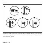
Page 163: ...handles 883 101 12 GRYD Manual To make sure the drawer is held firmly in place lock it to the drawer rails To do so you need to press the little platform below the drawer back into place you detached it earlier in step 1 ...

Page 164: ...just it A For adjustments of the drawer towards the top pull the drawer out to the far end and turn the small fixture mechanism to the right as shown in illustration A B For adjustments of the drawer towards the bottom pull the drawer out to the far end and turn the small fixture mechanism to the left as shown in illustration B ...

Page 165: ...e inside of the sidewall and move the rail further to the front of your furniture D Towards the inside of your furniture take the drawer box out of the rails loosen the two screws that are inside of the sidewall and move the rail further to the back of your furniture NOTE only loosen the sidewall screws in this step do not remove them Otherwise adjustment will be not possible ...

Page 166: ... that are inside of the distance and move the rail further to the front of your furniture D Towards the inside of your furniture take the drawer box out of the rails loosen the two screws that are inside of the distance and move the rail further to the back of your furniture NOTE only loosen the distance screws in this step do not remove them Otherwise adjustment will be not possible ...

Page 167: ...Ia IIa Ib IIb 342mm 470mm 470mm 342mm Ib You will build something similar to this DRAWERS WITH PUSH TO OPEN FOR GRYD ...

Page 168: ... 124 01 101 124 03 101 124 04 901 100 22 901 100 05 101 124 05 101 124 06 101 124 07 101 124 08 Drawers with push to open 883 101 13 GRYD Manual Here are the parts you will need Screw 4 x 20mm Distancer Screw Varianta 3 x 10mm Screw 4 x 25mm Drawer Frontplate Drawer Box 34cm deep shelf Drawer Box 47cm deep shelf Drawer Box 34cm deep shelf Drawer Box 47cm deep shelf ...

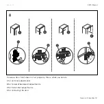
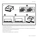
Page 169: ...integrate them with your furniture you have to separate the pieces first 1 Pull the little platform within the fixture construction at the bottom of the drawer as illustrated above 2 Hold the rails and carefully lift the drawer box 3 Pull the drawer box out 4 Place all items separately next to each other ...

Page 170: ...es that simplify the front mounting Attach the front to the box as illustrated above NOTE the pre drilled holes in the drawer box have a larger diameter than the screws you need The additional space can be used to find the perfect position for your front if it is not level with its neighbouring parts ...

Page 171: ...walls Use the second hole from the bottom of the compartment you want to place the drawer in Use the third hole from the bottom of the compartment you want to place the drawer in NOTE Again the hole in the rail is bigger than the screw itself You can use the space to level the drawer see step 10 and 11 IIa Ia ...

Page 172: ...4 P64 P65 P64 P65 Ib IIb 470mm 470mm 172 Drawers with push to open 883 101 13 GRYD Manual Screw the distancer P64 to the sidewalls Use the screw 4x20 P65 ...

Page 173: ...5 P14 P14 P64 Ib IIb 470mm 470mm 173 Drawers with push to open 883 101 13 GRYD Manual Screw the drawer rails to the distancer P64 Use the screw 3x10 P14 ...

Page 174: ...83 101 13 GRYD Manual Now it s time to connect the drawer with the rails again To do this pull the drawer rails towards you Place the drawer box on the slides as shown above The two zooms might help you with finding the exact position ...

Page 175: ...sh to open 883 101 13 GRYD Manual To make sure the drawer is held firmly in place lock it to the drawer rails To do so you need to press the little platform below the drawer back into place you detached it earlier in step 1 ...

Page 176: ...an adjust it A For adjustments of the drawer towards the top pull the drawer out to the far end and turn the small fixture mechanism to the right as shown in illustration A B For adjustments of the drawer towards the bottom pull the drawer out to the far end and turn the small fixture mechanism to the left as shown in illustration A ...

Page 177: ... Manual C Towards the outside of your furniture scroll the small back wheel at the bottom side of the drawer slides towards you D Towards the inside of your furniture scroll the small black wheel at the bottom side of the drawer slides away from you ...

Page 178: ......

Page 179: ...Mail support mycs com AT 43 800 070 423 CH 41 800 080 060 DE 49 800 100 40 50 FR 33 0 1 86 65 12 20 UK 44 330 808 7475 fb com mycscom instagram com mycs_com twitter com mycs_com pinterest com mycs_com QUESTIONS uk mycs com faq houzz com pro mycs com mycs gmb ...

Page 180: ...1 2 3 4 5 6 www mycs com ...

Reviews: