4.
To install the Receiver:
4a.
Connect the Receiver DVI port to the Monitor DVI port with a DVI compliant cable.
4b.
Connect the two Receiver USB 1.1 ports to a USB keyboard and mouse.
4c.
Connect the two Receiver USB 2.0 ports to other USB devices, such as a printer,
drawing pad, storage device, camera, etc.
4d.
If required, connect the Receiver audio-out and mic-in port to an audio/mic system
audio-in and mic-out port, respectively.
4e.
If the application is point-to-point, then connect one (1) Cat 5e/6 cable (or higher)
coming from the Transmitter, to the RJ45 LINK connector on the Receiver. If
transmitting over the network, use an Ethernet Switch between Transmitter and
Receiver.
5.
If the configuration is a multiple point-to-point (including point-to-multipoint) architecture:
5a.
You will need to use an Ethernet Switch with Gigabit ports and DHCP Server support.
In addition Jumbo Frame support is required.
Verify that the Ethernet Switch is
configured correctly and that the DHCP Server is enabled and that Jumbo Frame
is enabled
. See the operating manual for more information about configuring the
Ethernet Switch.
5b.
Connect all Transmitters and Receivers to the Ethernet Switch.
5c.
Use the DIP Switches to select a unique Device ID for each Transmitter present on the
network and configure each Receiver Device ID to the corresponding selected
Transmitter.
Note
: This step is not necessary if the MuxLab Pro Digital Network Controller
(500811) is used.
6.
Powering the Transmitter or Receiver via an external power supply is only necessary where
PoE (PSE) is unavailable. If PoE is unavailable, connect a 5 VDC power supply (500993 -
sold separately) to each Receiver and to an AC power outlet. Next connect each Transmitter
in the same manner. If power is present, the green power LED on each Transmitter and
Receiver will illuminate.
Note: Power ‘ON’ the KVM DVI over IP PoE Extender Kit only after all connections
have been made.
7.
Power ‘ON’ the DVI equipment and verify the image quality, sound if applicable, keyboard
and mouse functionality, as well as any additional USB connected devices.
8.
There are two basic hot key methods to switch a Receiver among different Transmitters. One
method is via an OSD (On Screen Display) menu, which can be called up by pressing the
hotkey sequence “Scroll Lock” three times in less than 0.5 seconds. This brings up the OSD
menu to select which Transmitter to connect with. The second method is via 16 different
hotkey sequences, with each one providing direct access to a preconfigured Transmitter. This
is available by pressing the CTRL Key with the port number pressed three times within 0.5
seconds. Port numbers follow the switch setting and are from 0 to 9 and q (10), w (11), e
(12), r (13), t (14) and y (15). Hotkeys can be modified from the device web server interface;
to find the IP address of the product use Bonjour Protocol.
9.
Please download and reference the 500771 Operation Manual found on the MuxLab website
(under the 500771 webpage) for further instructions on how to operate this device, including
how to configure and use the hotkeys and OSD.
10.
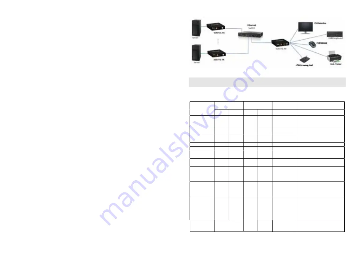
The following diagram illustrates a typical point-to-point LAN configuration.
Troubleshooting
The following table describes some of the symptoms, probable causes and possible solutions in regard to
the installation of the KVM DVI over IP PoE Extender Kit:
Symptom
Transmitter LEDs
Receiver LEDs
Probable
Cause
Possible
Solutions
Power
Link
Power
Link
No Image
OFF
OFF
OFF
OFF
No power
• Check power connections
• Check PoE Ethernet Switch
Setup
No Image
BLINK
OFF
BLINK
ON
Booting
• Wait until booting process is
finished
No Image
ON
OFF
ON
OFF
No Ethernet Link • Check Ethernet Switch Status
• Check UTP Cables
Info Screen
ON
OFF
ON
BLINK UTP Cable
• Check the Transmitter UTP cable
Info Screen
ON
ON
ON
OFF
UTP Cable
• Check the Receiver UTP cable.
Info Screen
ON
BLINK
ON
BLINK No Data
Connection
• Check if DIP Switch settings
match
Info Screen
ON
ON
ON
BLINK Wrong setting on
Receiver
• Check DIP Switch address of the
Receiver
Choppy Video
ON
ON
ON
ON
Configuration
• Check cable length
• Check the DVI Cable Quality
• Check if Jumbo Frame is enabled
on the Ethernet Switch
Image flickers
when powering
up nearby
equipment
ON
ON
ON
ON
Interference
• Use STP cables
Mouse or
Keyboard not
working or
freezing
ON
ON
ON
ON
USB Cable
• Check the USB Cable Quality
• Check that the Keyboard and
mouse are connected to the USB
2.0 Port.
• Do not use USB 1.1 ports in this
current release.
USB Speed Slow
ON
ON
ON
ON
Wrong Port
• Check that any additional USB
devices are connect to the USB
2.0 Port


