

© MuxLab Inc. 2013
3.
Verify that the distance between the CCTV IP PoE extenders is within MuxLab
specifications (see Specifications table).
4.
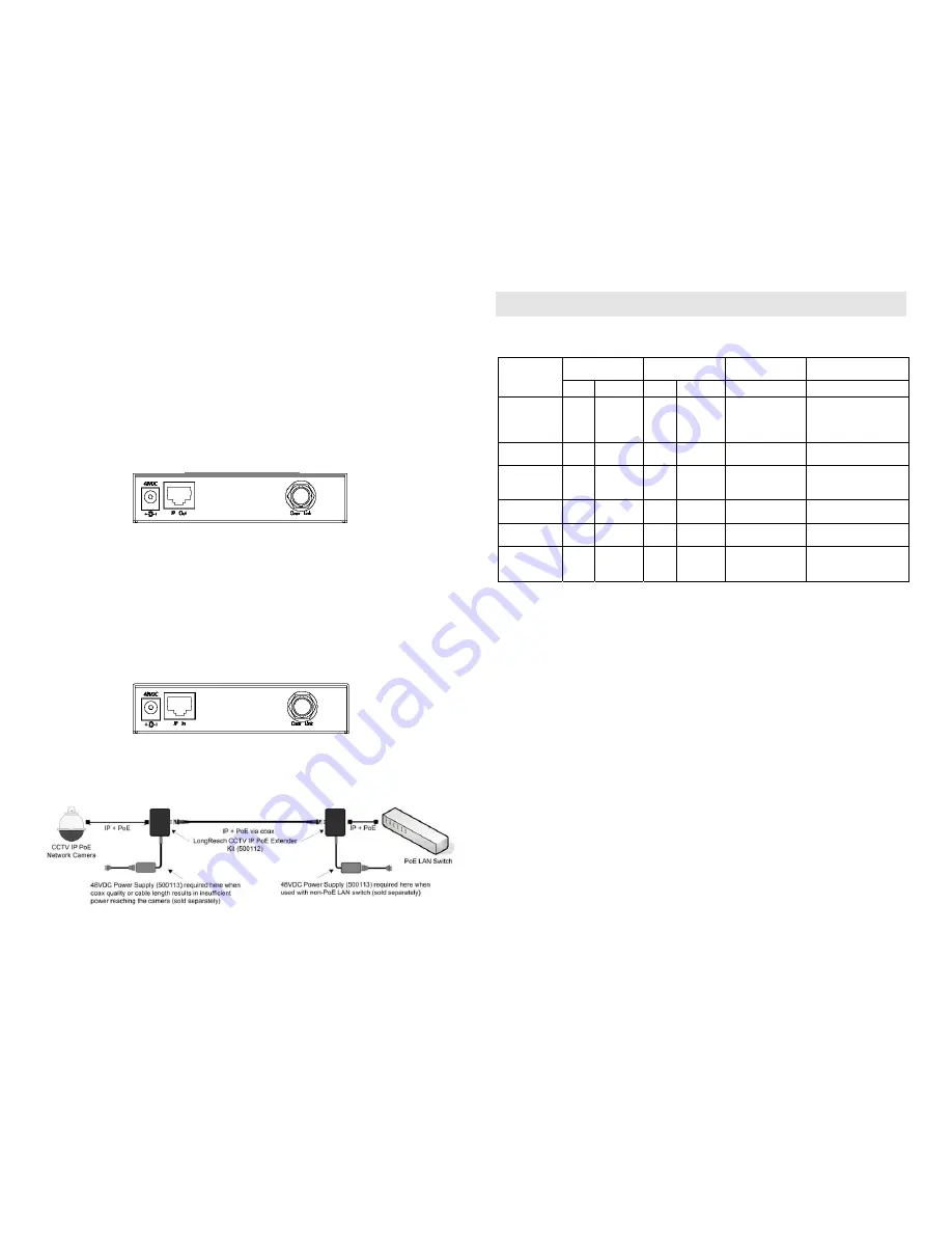
To install the Network Side Device:
3a.
Connect the extender to the PoE Ethernet Switch with a UTP Cable.
Note: If the Ethernet Switch is not PoE; you will need to connect a PoE Power
Supply (500113) to the Network Side Device.
3b.
Connect one (1) length of RG59 or RG6 coaxial cable to the COAX
LINK connector on the Extender.
5.
To install the Camera Side Device:
4a.
Connect the extender to the camera with a Cat5e/6 cable.
Note: If the quality or length of the coaxial cable reduces the power to a level that
is insuffiicent to power the camera, you will need to connect a PoE Power Supply
(500113) to the Camera Side device.
4b.
Connect one (1) length of RG59 or RG6 coaxial cable to the COAX
LINK connector on the Extender.
6.
Power on the equipment and verify the image quality. The following is a diagram
of a typical configuration.
Troubleshooting
The following table describes some of the symptoms, probable causes and possible solutions
in respect to the installation of the CCTV IP PoE Coax Extender Kit:
Network Side
LEDs
Camera Side
LEDs
Probable Cause
Possible
Solutions
Symptom
Power IP Traffic Power IP Traffic
No Image
OFF
OFF
OFF
OFF
No power
• Check if the Ethernet
switch is PoE.
• Check the power
connection.
No Image
ON
OFF
OFF
OFF
Coaxial Cable
• Check the coaxial
cables.
No Image
ON
OFF
OFF
OFF
Distance
• Check the coaxial
cables length and
quality.
No Image
ON
OFF
ON
OFF
UTP Cable
• Check the UTP Cable
pin out.
No Image
ON
ON
ON
ON
No Traffic
• Check network
configuration.
Choppy Image
ON
BLINK
ON
BLINK
Distance
• Check cable length
• Check the coaxial
cable quality.
If you still cannot diagnose the problem, please call MuxLab Customer Technical Support at
877-689-5228 (toll-free in North America) or (+1) 514-905-0588 (International).