VJ-1608 Hybrid INSTALLATION MANUAL
VJ1608HYE-I-00
4
1
3
2
1
2
2
1
2
2
1
2
1
2
2
1
2
3
1
2
3
1
1
3
2
1
2
1
4 Installation
Procedures and environment for installing this product
are explained.
4.1 Installation environment
Install this product to the appropriate place with refer-
ence to the following.
Do not install the printer in the follow-
ing places where there is a possibility
that the printer may be damaged or
might fall or be fallen by chance.
On a shaky stand
Slanting location
Places where vibration of other machines
etc. is transmitted.
Do not stamp on the printer or do not
place heavy things on top of it. The
printer may be damaged or might fall
or be fallen by chance.
Cover the printer with blanket and cloth
like tablecloth and do not close the vent.
If the vent is closed, the printer could
accumulate heat inside and may cause
fire.
Do not install the printer in a location
that has high humidity or is dusty.
It could lead to electric shock and fire.
4.1.1 Installation environmental condition
Select an installation location in accordance with the
table below.
For temperature and humidity, avoid locations
such as the following. There is a possibility that
the print quality will be affected.
Places where temperature or humidity may
rapidly change, even though within the required
conditions.
Places that receive direct sunlight, increased illu-
mination or direct air, for example from an air
conditioner.
To keep the temperature and humidity constant, in-
stall this product in a location where the air condi-
tion is adjustable.
(Cont'd)
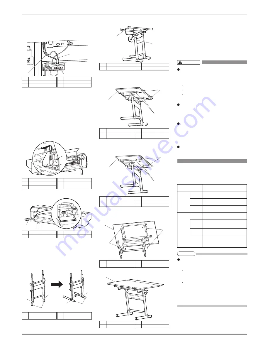
3. Looking at the rear of the printer, attach the short
air tube to the left side of the solenoid valve unit
and the long air tube to the right side of the sole-
noid valve unit.
3.4 Detaching fastening materials
This printer has fastening materials in the place shown
below.
Detach all protective materials in accordance with the
following steps.
1. Remove all tapes from each cover.
2. Open the front cover, then remove a screw from
the head unit fastening material (metal plate) and
remove the material.
3. Open the left maintenance cover, then place the tray.
3.5 Assembling the media-feed table
Follow the procedure below to assemble the Media-
feed table.
1. Loosen the knobs fastening the legs and set the
legs as shown in the illustration.
2. Loosen the angle lever and set the Media-feed table
base so that it is horizontal.
3. Loosen the knobs on the base and extend the draft-
ing board supports to be longer than drafting board
R, and place drafting board R on the base.
4. Shorten the drafting board supports against the
drafting board R and tighten the knobs.
5. Fasten drafting board R by using the drafting board
fastening screws.
6. Assemble Media-feed table F in the same manner.
More than 2940 Pa (300 kg/m2)
Power
Specifica-
tion
Environm-
ental
conditions
Floor strength of
installation place
Power
Supply
Frequency
Range
AC 90 V to 132 V / 198 V to 264 V
50/60Hz ± 1Hz
Power
capacity
Change
rate
Operative
condition
Archiving
condition
(Ink filled)
Printing
accuracy
coverage
Main: 8.5 A
Heater: 10.0
A
Temperature: 20 °C to 32 °C
Humidity: 40 % to 60 %, No Condensation
Temperature: 22 °C to 30°C
Humidity: 40 % to 60 %
Temperature: within 2 °C per hour
Humidity: within 5 % per hour
When Sleep Mode is ON:
Temperature: 10 ° C to 40 °C
Humidity: 20 % to 80 % ,
Storage life: four days (32 °C or higher)
No.
Name
1
Head unit
2
Screw
No.
Name
3
Head unit fastening
material (metal plate)
No.
Name
1
Maintenance cover (Left)
No.
Name
2
Tray
No.
Name
1
Legs
No.
Name
2
Knobs
No.
Name
1
Angle lever
No.
Name
2
Media-feed table base
No.
Name
1
Drafting board R
No.
Name
2
Drafting board fastening screws
No.
Name
1
Media-feed table F
No.
Name
1
Solenoid valve unit
2
Short air tube
No.
Name
3
Long air tube
No.
Name
1
Drafting board R
2
Drafting board supports
No.
Name
3
Knobs
No.
Name
1
Drafting board R
2
Drafting board supports
No.
Name
3
Knobs
WARNING
NOTE
All manuals and user guides at all-guides.com


