background image

FlexiSTARTER Quick Start Guide 


ValueCut USER MANUAL


98 

VC2E-A-00 

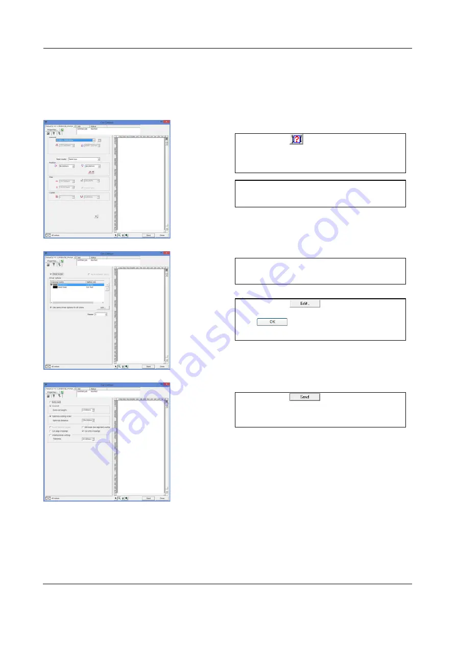
8.10.3 Cut Contour 

The basic setup is the same as the Cut/Plot window. 
The ValueCut executes to cut the contour in the following process. 


1. 

Click on 

  to detect and present 

media size attached to the ValueCut. 

2. 

Select "Send now" in the Send mode 
blank. 

3. 

Place the check mark in the Weed 
border. 

4. 

Click on 

, then in the opened 

window select "Cut First". Click on 

  to close the window. 

5. 

Click on 

  to send the 

ValueCut cutting data. Then, the cutting 
job may start. 

Summary of Contents for ValueCut II Series

Page 1: ...Rev No VC2E A 00 USER MANUAL Sign Cutting Plotter Read This Manual Before Using The Plotter VC2 600 VC2 1300 VC2 1800...

Page 2: ...ted in any form or by any means except for personal use without the permission of MUTOH INDUSTRIES LTD The product and the contents of this publication may be changed without prior notification MUTOH...

Page 3: ...utions and instructions below Caution SAFETY PRECAUTION For safety concern please always hold the cutter firmly from the bottom while moving it Do not move the cutter by clasping the depression area o...

Page 4: ...areful to make sure that clothing and hair do not get caught Always connect the power cable to a grounded outlet Always use the accessory power cable which is provided Do not wire the power cable so t...

Page 5: ...hown below This will prevent you from disabling the pinch roller as the stop bar will not reach the correct position and therefore will not be functioning In case the grips clipped together due to you...

Page 6: ...t Side View 14 2 Installation 15 2 1 Precaution 15 2 2 Stand Flexible Media Support System VC2 1300 1800 16 2 3 USB Cable Tie and Saddle 22 2 4 Desktop Flexible Media Support System VC2 600 24 2 5 Ins...

Page 7: ...6 5 2 2 Notice for Registration Marks 56 5 2 3 AAS II on ValueCut 57 5 3 AAS Offset Test 61 5 4 Registration Mark Offset Range 62 5 5 Contour Cutting 63 5 6 Tips for AAS 66 6 Maintenance 67 6 1 Cleani...

Page 8: ...ar 88 8 7 Create the Character 89 8 7 1 Cut Plot Window 90 8 8 Cut the Character 91 8 9 Create Date of the Contour Cut Line 93 8 9 1 Procedure of the cut contour 93 8 9 2 Read in the data of the Adobe...

Page 9: ...mm 1 97 1 594 mm 62 7 VC2 1800 for media width 300 mm 11 8 1 990 mm 78 3 1 2 Package Items The package of the ValueCut model contents the items listed below please check carefully If you find any ite...

Page 10: ...V 12 pieces of M6 screws V 1 piece of 3 mm L shape hexagon screw driver V 1 4 Media Basket VC2 1300 1800 only Optional for VC2 600 2 pieces of Basket Arm 2 pieces of Basket Rod 1 piece of Basket 4 pi...

Page 11: ...otters Triple port connectivity provides you with greater flexibility Up to 600 gram cutting force Up to 1 530 mm 60 inch per second cutting speed at 45 direction Guaranty 10 meter tracking User frien...

Page 12: ...talled blade and pen with AAS module Slicer Groove slice off the extra media easily along this groove Platen provides the surface for holding and supporting media while performing cutting Alignment Ru...

Page 13: ...ring cutting Lever Raises or lowers the pinch rollers Roll Holder holds and supplies the roll media for cutting Roll Holder Guide Bushes serve to keep the roll media in place when media is pulled from...

Page 14: ...ert the AC power cord Serial Interface Connector RS232C used to connect the cutting plotter to a computer through a serial interface cable USB Connector used to connect the cutting plotter to a comput...

Page 15: ...orkshop The relative humidity of the working environment should be between 25 and 75 Protecting the machine from dust and strong air current Preventing the machine from direct sunlight or extremely br...

Page 16: ...2 pieces 2 pieces of base beams 2 pieces of side beams 1 piece of stand beam 2 piece of roll holder support 20 pieces of M6 screws 1 piece of 4 mm L shape hexagon screw driver 1 piece of Installation...

Page 17: ...he beam comes with a break while the rear one is on its own Step 3 Place the stand beam upright on the T stand and follow number 1 2 to assemble See Figure 2 4 2 5 There is hexagon socket head screws...

Page 18: ...e the cutting plotter from the carton Position your stand under the plotter on the bottom of the plotter there is one hole on each side in the position corresponding to the locating pins so the locati...

Page 19: ...the stand and then tighten them up as shown in Figure 2 7 You could decide roll holder support s position by inserting into different holes Step 7 Place roll holder 1 into the holes in the roll holder...

Page 20: ...fter unpacking roll holder 2 Figure 2 9 Step 9 Insert the end of the roll holder without the damper into the left roll holder support and then insert the end of the roll holder with the damper into th...

Page 21: ...w on the damper until it is securely attached to the right roll holder support Figure 2 11 Step 11 Lastly the complete picture will be shown like below Figure 2 12 Step 12 Please refer to user manual...

Page 22: ...ly for the stands with Flexible Media Support System only Step 1 Insert the cable tie into the upper hole of cable saddle from bottom to top This side up Step 2 Place the USB cable into the cable tie...

Page 23: ...ValueCut USER MANUAL Installation 23 VC2E A 00 Untied way pull out the cable tie pull up the pin release the cable tie Pull out the cable tie Pull up the pin Release the cable tie...

Page 24: ...pieces of M4 screws 12 pieces of M6 screws 1 piece of 3 mm L shape hexagon screw driver 1 piece of 4 mm L shape hexagon screw driver 1 piece of 5 mm L shape hexagon screw driver for adjusting the scr...

Page 25: ...er Assembly beside the bottom of the machine Then insert the M6 screws into the holes of Roll Holder support assembly and tighten them with 5 mm L shape screwdriver Like Figure 2 15 Step 5 Place the t...

Page 26: ...A 00 2 5 Instruction of Damper Roller Step 1 Turn the wheel as instructed below to adjust damping The bigger the number is the stronger the damping The volume symbol sticker indicates the damping leve...

Page 27: ...rms 2 pieces of basket rods 1 piece of basket 2 pieces of fixtures for basket arms 8 pieces of M3 screws 1 piece of 2 mm L shape hexagon screw driver Step 2 First place the basket arms beside the stan...

Page 28: ...ket holes See Figure 2 21 Step 4 Loosen the basket screws from the basket arms Position the basket rod in front of the basket arms and insert the basket screws into the holes on the basket rod and tig...

Page 29: ...ValueCut USER MANUAL Installation 29 VC2E A 00 Step 5 The complete Media Basket System will be like Figure 2 23 Figure 2 23...

Page 30: ...n the accessory pack Follow the instruction below to install a new cutting pad when the existing pad is worn out Step 1 Carefully remove the cutting pad from the unit Step 2 Remove the remaining adhes...

Page 31: ...Cut USER MANUAL Installation 31 VC2E A 00 Step 3 Attach the new cutting pad to the groove after unrolling it and removing the backing sheet and the installation process is completed Figure 2 26 Figure...

Page 32: ...the bottom of the blade holder Figure 2 30 Step 3 Adjust the blade tip to suitable length by screwing Blade tip adjustment screw clockwise or count clockwise Figure 2 31 Figure 2 31 Figure 2 30 Tips...

Page 33: ...e eject pin to eject blade when the blade needs to be replaced Note The blade will lose its sharpness after a period of usage the cutting quality might be affected By increasing the cutting force it m...

Page 34: ...adjust the blade length for 0 00 mm 5 00 mm Figure 2 34 Figure 2 35 Follow the steps below to adjust the length of the blade 1 Keep the blade tip within the blade holder before you start adjusting 2...

Page 35: ...hich direction CW clockwise or CCW counterclockwise you should turn the adjustment knob EG Turn CW 5 is telling you that you should turn the knob for 5 units clock wisely Figure 2 36 Figure 2 37 5 The...

Page 36: ...mputer and how to set up the computer cutting plotter interconnection Figure 2 38 Note When USB connection is enabled both parallel port and serial port will be disabled automatically Serial Interface...

Page 37: ...ssages Power LED To indicate the power status light up power on light off power off 4 Arrow Keys To move position select function or change setting ENTER To set item or register the immediately preced...

Page 38: ...3 2 Menu in On line mode Power On ValueCut in processing Sending data PAUSE FORCE SPEED OFFSET DATA CLEAR TOOL SELECT Top menu Speed Force Offset Length Width Tool set Metric The product name of your...

Page 39: ...ne Mode Press ON OFF LINE to switch to the offline mode High Medium Low CUT TEST FORCE 5 600 with an increment of 5 gram force OFFSET DATA CLEAR Speed 3 153 with an increment of 3 cm s SPEED 0 000 1 0...

Page 40: ...crement of 1mm OverCut 0 00 1 00mm with an increment of 0 05mm English Fran ais T rkce Polski Japanese Deutsch Italiano Espa ol Portugu s Both Expanded Mode Length Expanded Mode Width Expanded Mode Bo...

Page 41: ...um Tracking 150 meters Single To measure media width and length Maximum Tracking 10 meters POWER To indicate the power status Arrow Keys 1 To move the tool carriage position on X or Y axis 2 To select...

Page 42: ...levels while the tool move from endpoint to next start point at horizontal moving High Medium Low Medium Up Speed To set or modify tool up speed at horizontal moving 3 153 cm sec 3 cm sec per step 72...

Page 43: ...ise you should turn the adjustment knob EG Turn CW 5 is telling you that you should turn the knob for 5 units clock wisely The value on the screen will be 0 0 when the blade length is perfect and no m...

Page 44: ...ct if the rear paper sensor is covered to determine the following process when it is enabled the cutter will detect if the material has covered the rear paper sensor under the Roll and Edge mode when...

Page 45: ...e IP Address of your cutting plotter MAC Address Shows the MAC Address of your cutting plotter Firmware Version To display the version number of Firmware and FPGA code Select Language To select displa...

Page 46: ...inch rollers from either the front side or the backside The alignment rulers on the platen extension will help you to adjust the media precisely Note Be sure that the media must cover the paper sensor...

Page 47: ...ms are Figure 4 3 Figure 4 4 X Incorrect Note 1 Always adjust the position with the pinch roller raised 2 Move the pinch roller by applying force at the rear portion of the pinch roller support 3 Do n...

Page 48: ...ollers Step 5 The media sizing selection menu Roll Edge Single appears on the control panel Use key to choose Single 4 1 2 Loading the Roll Media Step 1 Put the roll media guide bushes on two roll hol...

Page 49: ...n of the roll media ensure that media flanges are able to run in the grooves of media guide bushes Figure 4 8 Option B Insert the two roll holders into the roll media support set then place the roll m...

Page 50: ...backward to lower down the pinch rollers Step 7 Fix roll media guide bushes on the roll holder to secure the roll media Step 8 The media sizing selection menu Roll Edge Single appears on the control...

Page 51: ...he media length is less than 4 meters leave the margin of 0 5 mm 25 mm in the left and right edges of the media Figure 4 12 If the media length is greater than 4 meters leave at least 25 mm margin on...

Page 52: ...ARROW key to move the tool carriage to the position where you like Then press the ENTER key to perform Cut Test Note At the same time the new origin is also set at the cutting test position When the...

Page 53: ...lot When you are making a long plot with a roll of heavy and wide vinyl paper you need to use the AUTO UNROLL MEDIA function The following parameter settings are to help users get the best cutting qua...

Page 54: ...Specification About the Tool in Appendix After you notice all the above you ll enjoy your gigantic signs production 4 6 When Completing the Cutting Job After completing the cutting job raise the shee...

Page 55: ...otters feature a standard Automatic Aligning System AAS II to guarantee precise contour cutting quality by detecting the registration marks printed around the graphic Notice Avoid any kind of light so...

Page 56: ...hen to use We suggest white media for best cutting result It is not necessary to perform media calibration every time unless the registration marks on the printed media become undetectable in AAS sens...

Page 57: ...printed on colored medium Dirty or creased medium surface 5 2 3 AAS II on ValueCut There are three types of AAS II mark patterns 4 Point Positioning Segmental Positioning and Segmental cutting Note t...

Page 58: ...arks for each individual image to ensure the contour cutting precision Command Esc D3 XCopies YCopies Space Layout 2 Segmental Positioning In addition to 4 original points the intermediate registratio...

Page 59: ...eding direction of the material when performing contour cutting Figure 5 1 shows the Registration Mark detection sequence when the material is fed in the standard way 1 2 3 4 while Figure 5 2 is how V...

Page 60: ...Automatic Aligning System ValueCut USER MANUAL 60 VC2E A 00 Figure 5 1 Figure 5 2...

Page 61: ...be made you can change the offset value by following the steps Measure the offset values from the printed line and the actual cutting line Enter the AAS Offset under MISC function for the values you j...

Page 62: ...detected Deviation exceeds the range below will lead to detection failure Media feeding direction Media feeding direction X Value Y Value X Valu Y Valu Note Before adjusting the AAS II settings pleas...

Page 63: ...s Step 1 Using FlexiSTARTER supplied with your ValueCut or a cutting software compatible with ValueCut create a contour cutting job file and add registration marks described on 5 2 3 Note To create a...

Page 64: ...media The AAS Layout Instruction Auto detection function on the 1st mark covers the grey area Suggested 30 mm margin on both left and right sides of media sheet To prevent media sheet from dropping o...

Page 65: ...se make sure the media is fed with correct direction Use the JOG key to move the cursor and then adjust the location of the cutter holder to the inside corner of the origin mark Switch to online mode...

Page 66: ...marks locating on the tracks of pinch rollers Make sure the edge of the media is not bent up when detecting registration marks By adjusting the location of the cutter holder to the inside of the corne...

Page 67: ...e with a lint free cloth If necessary with a damp cloth immersed in water or alcohol Dry and wipe any remaining residue off a soft lint free cloth Wipe all dust and dirt from the tool carriage rails U...

Page 68: ...Rollers 1 If the pinch rollers require a thorough cleaning use a lint free cloth or cotton swab to wipe away the accumulated dust from the rubber portion of the pinch rollers To prevent the pinch rol...

Page 69: ...ord connected to the power connector properly Does the power LED still illuminate Solutions If the LCM is able to display the message the cutting plotter should be in a normal condition Switch off the...

Page 70: ...blem and re power on to reboot system This message indicates that there might be an obstruction to carriage relating to a problem on the Y axis the carriage moving direction Correct the problem and re...

Page 71: ...y pressed when a clip sound is heard and pull the bottom release grip at the same time as the pictures shown below This will prevent you from disabling the pinch roller as the stop bar will not reach...

Page 72: ...the media is correctly loaded Refer to the alignment ruler 4 The media lifts Step 1 Stop the operation Step 2 Move the pinch rollers to the side Step 3 Pull the lever up Step 4 Reload the sheet and en...

Page 73: ...Refer to Chapter 2 Connecting your cutting plotter Yes No Try the communication between your cutting plotter and computer If it still does not work have your cutting plotter serviced Refer to the MIS...

Page 74: ...erface match the requirements of your software Does your software recommend using a different cable Does the software vendor provide a sample file If it is not compatible with your ValueCut use softwa...

Page 75: ...tain an optimum blade force Refer to Chapter 4 3 Cutting Force and Offset Adjustment Is the tool offset set up properly Yes No Adjust the tool offset to obtain an optimum value Is there any dirt adher...

Page 76: ...ows 10 Pro 32 bit or 64 bit Windows 10 Home 32 bit or 64 bit Windows 8 8 1 32 bit or 64 bit Windows 8 8 1 Pro 32 bit or 64 bit Windows 8 8 1 Enterprise or 64 bit Windows 7 Home Premium 32 bit or 64 bi...

Page 77: ...oud 8 2 2 Install FlexiSTARTER ValueCut Edition Please insert the DVD for installation of the ValueCut into the computer Please open it and click on 1 English Click on 2 Install FlexiSTARTER ValueCut...

Page 78: ...DVD case and press the key If this is the first time to use FlexiSTARTER you may have to activate the software by internet Please press the Open in Web Browser Now key Internet Explorer will boot up a...

Page 79: ...ade a mistake on your E mail address input other E mail address to 6 and press the Send key There is a link for account registration attached on the E mail Access to this link and create your account...

Page 80: ...NUAL 80 VC2E A 00 Once you complete the account registration continue the activation Press the Activate Now key Below screen will show up if the activation is completely done Go back to the installer...

Page 81: ...ide 81 VC2E A 00 Go back to the installer screen and press the key Authenticate the license via internet License is certified if Licensing Successful shows up If you press the key license information...

Page 82: ...installed the FlexiSTARTER that makes it possible to create and edit cutting date and the Production Manager that allows you to manage cutting job from the FlexiSTARTER ValueCut and control device of...

Page 83: ...USB cable 1 2 3 1 You can see Mutoh selected in the box saying What is the brand name of your vinyl cutter 2 Select a model of the ValueCut you have in the box saying What is the model name of your Mu...

Page 84: ...ving job that finishes running The Production Manager window can hold a job following the figure below This is how to leave cutting job in the screen after the cut 1 2 1 Select a model 2 Select Defaul...

Page 85: ...d in the Production Manager Open the Preferences window from the Edition menu of the Production Manager and change settings as follows 1 2 1 Change the unit 2 Select the precision and press the button...

Page 86: ...ng the instruction written in blue 1 2 4 5 6 3 Names of the each part in this screen 1 Main Menu 2 Standard Toolbar 3 Design Area 4 Main Toolbar 5 View Toolbar 6 Swatch Table 7 Cloud page Origin Click...

Page 87: ...n the Design Central window The Fill Stroke Editor screen allows you to set up a color and a line type 8 6 2 Standard Toolbar Only usable icons are active Open a new window Open a file Save a file you...

Page 88: ...that may appear when you click on them for a while Select Tool that selects an object Text Tool that makes it possible to enter text Bezier Path Tool that creates a path Rectangle Tool that makes a r...

Page 89: ...the design area discretionally 2 Assign 100millimeters in height in the Design Central window 3 Then enter ABC from the keyboard 4 Click on in the standard toolbar then the Cut Plot window may open At...

Page 90: ...0 8 7 1 Cut Plot Window The Cut Plot window has four tabs as follows General tab Set up Material size Position Size Copies Panel tab Set up for job that exceeds media size Panel size Title Overlap Opt...

Page 91: ...ewhere around A3 size sheet sideways to the ValueCut 8 8 Cut the Character Execute cutting job in the Cut Plot window with each of the tabs as follows 1 Click on then media size loaded to the ValueCut...

Page 92: ...eCut USER MANUAL 92 VC2E A 00 4 Place a check mark in Weed border 5 Click on then the window may open Select Cut First in and click on and close the window 6 Click on to send cutting data to the Value...

Page 93: ...Extract the contour cut line from the data red in 3 Place the contour cut mark that is ValueCut readable around the contour cut line extracted 4 Print the cutting data of the contour cut from the pri...

Page 94: ...of the contour cut line 1 Hover the mouse pointer over the whole image 2 Select Cut Contour from the Effects menu 3 Set up in the Design Central window as follows a Select Contour b Make length from t...

Page 95: ...the standard cut The ValueCut detects four reg mark and makes the alignment Mutoh Segment Positioning For the purpose of a long length plot cut this Mutoh segment positioning prints the reg marks at 5...

Page 96: ...ur 2 The contour cut mark may be created Assign a kind of the mark from the Design Central window This time Mutoh 4 Point Positioning is applied 3 Set up in the Design Central window as follows a Sele...

Page 97: ...rom the File menu and print cutting data of the cut contour As to the printing procedure refer to the printer manual you use 8 10 2 Cut contour window Select Cut Contour from the File menu then the Cu...

Page 98: ...ut the contour in the following process 1 Click on to detect and present media size attached to the ValueCut 2 Select Send now in the Send mode blank 3 Place the check mark in the Weed border 4 Click...

Page 99: ...nts Use the ball point pen holder instead of scope Set the ball point pen to pen head before plotting Adjust the tip of the ball point pen on top the middle position of the registration mark If it is...

Page 100: ...e plotting starts and at the same time plotter side display will change to below Move the pen head pen tip to registration mark 1 from the plotter side JOG key Press ENTER key at the point the registr...

Page 101: ...orm Working with Color Eyedropper Modify Color Libraries Measure Color Create Duotone Swatch Create CMYK Swatch Create Current Palette Swatch Using Fill Stroke Editor Patterns Gradients Overprint Work...

Page 102: ...r Trapping Graphic Styles Contour Working with Measurements and Labels Dimensions Labels Automatic Dimension Dimension to Page Configuring the System for Color Printing Color Settings Soft Proof Cutti...

Page 103: ...the plotter after the FlexiSTARTER you may not be able to send data to the plotter Follow the procedures below to set the output port to USB_Printer_0 again Open the Production Manager Right click on...

Page 104: ...re than once you will see higher number added at the end of USB_Printer_ e g USB_Printer_2 Choose the port name with the highest number on the list Do not choose the three digit number if any e g USB_...

Page 105: ...than 3 m Check the setting of the serial port Flexi and plotters have to match the communication setting Check the Communications setup Refer to the 8 4 Add Device by Using the Production Manager and...

Page 106: ...P GL HP GL 2 Mechanical Resolution 0 006 mm Software Resolution 0 025 mm Distance Accuracy 0 254 mm or 0 1 of move whichever is greater Repeatability 0 1 mm Control Panel LCD 20 digits x 2 lines 14Key...

Page 107: ...Cap 0 50 mm blade offset and 2 5 mm blade diameter For cutting thin sandblast mask and stencil The blade with sharp angle and special design allowing it to maneuver around sharp corners The blade is...

Page 108: ...ng to the reference point OFFSET is the distance that the blade tip is displaced from the centerline of the blade Protrusion Length of the Blade Length of protrusion t1 t 2 2 but for your convenience...

Page 109: ...Red Cap 45 0 25 1pce box VC2 CBGR1 Cutting Blade Green Cap 60 0 5 1pce box VC2 CBBU1 Cutting Blade Blue Cap 60 0 25 1pce box VC2 CBBK1 Cutting Blade Black Cap 50 0 175 1pce box VC2 CBYE1 Cutting Blad...

Page 110: ...ional Items Part Number Item Name VC2 STD600 Stand for VC2 600 with Basket VC TBL Add on flat table for VC2 600 VC RS RS 232C cable VC USB USB cable For more information about the options and the supp...

Page 111: ......

Page 112: ......

Reviews: