background image

20

When scanning speed set to 200ms/div or a faster time base, after pressing “S” button, user will immediately

hold the last waveform on the screen. If the instrument is set to 50ms/div or a slower time base, the instrument will
hold the waveform when scanning by rolling. The instrument will automatically transmit the earliest data display to
the left of the screen to maintain the continuity of waveform.

Instructions!

After waveform is held, press F4 button to activate cursor measurement function (fast movement

of cursor will probably cause

blurring screen due to delayed response of monitor; in such case,

user may exit and get back to measurement status for recovery

); press “S” button for 2 seconds to

enter into database and save the waverform. Once waveform is held, any adjustment of waveform
will be disabled. If you need to change scanning time base, vertical amplitude, coupling means and
wave position etc., you may press “S” button and restart the collection of waveform data.

Storage and reading of waveform of signals

The OSC database of the instrument is provided with a memory space for 50 OSC waveform data. The operation
method of the storage is as follows:
1. Press “S” button for 2 seconds and enter into the database.
2. If user needs to save current waveform, user may press “S” button to hold current waveform, or use single-time
scanning to get held waveform; press “S” button again, and the monitor will list the status of storage position of the
first page.

Summary of Contents for MDS8207

Page 1: ...Oscilloscope Multimeter User s Manual...

Page 2: ......

Page 3: ...please carefully read this manual especial the part of Safety Instructions Please also keep this manual property for future reference Contents SAFETY INSTRUCTIONS 1 INTRODUCTION TO THE INSTRUMENT 4 Ma...

Page 4: ...l 12 About the trigger mode 13 Prompt message of scanning status 13 Trigger operations of single scan 14 Cursor measurement reading function 15 Automatic measurement of waveform 17 Automatic setting o...

Page 5: ...0A 32 Frequency counting and measurement of duty ratio 33 Resistance measurement 35 Capacitor measurement 38 Temperature measurement 39 Measurement of amplification factor of triode 39 Storage and rea...

Page 6: ...ot touch the metal part of the probe of test leads with your finger 2 Do not operate the multimeter in high temperature moist rainy inflammable and explosive environment or when the instrument is wet...

Page 7: ...t measurement of circuits with a voltage of over AC 250V 8 When measuring functions are pointed at the gears of current resistance continuity test diode capacitance and etc never bridge the test leads...

Page 8: ...e avoid touching the testing end of test leads when there is voltage in the terminal s Instruction Instruction suggests that special attention should be paid during operation as wrongful operation wil...

Page 9: ...eform without taking into account the waveform parameter and distortion REL effectively eliminate the lead resistance distributed capacitance and interference signal The functions include DC AC voltag...

Page 10: ...range and work mode The option menu displayed on the LCD serves as the prompt for action R Waveform capture button S Data save button Instrument switch AC DC Voltage Frequency Duty ratio Resistance Di...

Page 11: ...operation for a set period of time the instrument will get into automatic sleep To turn off the function of automatic sleep user may press the R button and then rotate the rotary knob to turn on the i...

Page 12: ...ided for the testing rod of the multimeter it hard to thoroughly eliminate the interference when using the testing rod of the multimeter for waveform test To meet the needs of high quality test user m...

Page 13: ...lows Horizontal adjustment Vertical adjustment Triggering control Cursor function TIME VOLT TRIG CURS F1 F2 F3 F4 1 Press F1 button TIME to enter into sub option menu of time base setting and adjust t...

Page 14: ...rizontal position EXIT POS F1 F2 F3 F4 1 Press F1 button EXIT to exit the sub option menu of time base setting and back to the main option menu 2 Press F2 button and F3 button to adjust the time base...

Page 15: ...sition Back Adjustment of horizontal position Center the horizontal position EXIT RESET F1 F2 F3 F4 1 Press F1 button EXIT to exit the sub option menu of adjustment of waveform horizontal position and...

Page 16: ...n option menu 2 Press F2 button and F3 button to adjust the vertical amplitude V div Instruct ions To ensure the stability of circuit inside the instrument the movement of adjustment of sensitivity ma...

Page 17: ...level Under the sub option menu of trigger setting press F4 to enter into sub option menu of adjustment of trigger level Back Adjustment of trigger level Reset of trigger level EXIT RESET F1 F2 F3 F4...

Page 18: ...mode to monitor low frequency irregular signal or observe the amplitude of signals such as waveform of DC power etc Normal After trigger signals are detected the scopemeter will start collecting wavef...

Page 19: ...in the following steps 1 Adjust the vertical amplitude V div and horizontal amplitude to adapt to the waveform to be collected 2 Select appropriate trigger level gradient and then select single trigge...

Page 20: ...adjustment of trigger mode and adjust the trigger mode to automatic mode or normal mode Cursor measurement reading function The cursor measurement reading function can be used to measure the voltage...

Page 21: ...lows the measurement of voltage difference between the upper and lower cursors i e the crest of measured waveform peak value The sub option of voltage difference V measurement is as follows Back Adjus...

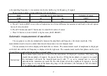
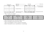
Page 22: ...e accurate than visual observation or cursor measurement The measurement result is displayed beneath the waveform The measurement result of amplitude is displayed on the left side and that of frequenc...

Page 23: ...ally set the vertical horizontal amplitude and the trigger level If you need to optimize the display of waveform you may make further adjustment manually If the instrument cannot find appropriate scan...

Page 24: ...of holding waveform is to hold the current data or waveform so as to make close observation easier The current wave also has to be held before it is stored into database There are two methods for hold...

Page 25: ...back to measurement status for recovery press S button for 2 seconds to enter into database and save the waverform Once waveform is held any adjustment of waveform will be disabled If you need to chan...

Page 26: ...p Page down Delete Save ERASE SAVE F1 F2 F3 F4 a Press F1 button to select the next data position in order b Press F2 button to select the next page in order c Press F3 button ERASE to erase the wavef...

Page 27: ...has been saved the original waveform will be replaced Therefore user has to be careful during operation so as to prevent loss of useful data After accessing the memory waveform reading function all st...

Page 28: ...ge up Page down Delete Cursor measurement ERASE CURS F1 F2 F3 F4 a Press F1 button to read the previous waveform b Press F2 button to rest the next waveform c Press F3 button ERASE to delete the wavef...

Page 29: ...ration methods When switching measurement functions please make sure to keep the probe of test leads away from the test point Basic content displayed under mutlimeter mode The following are the basic...

Page 30: ...follows thef ollowing circulation order voltage AC DC frequency duty ratio resistance diode continuity capacitancetemper aturetriodemA current AC DC 10A current AC DC AC waveformDC waveform For multi...

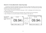
Page 31: ...occasions where a certain measuring range shall be fixed user may perform the following operations 1 Press R button and the mark of automatic measuring range AUTO will disappear and the instrument en...

Page 32: ...ll be saved as the reference value Then the relative value mode is activated 2 The value displayed on the screen is the difference between the current measured value and the expected reference value 3...

Page 33: ...2 seconds to access to database function In this way the data is saved 2 Under the data holding state a small window dynamic data window will appear on the upper right corner of the screen The data in...

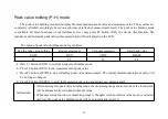
Page 34: ...easurement Stop measurement Reset peak value EXIT RUN STOP RESET F1 F2 F3 F4 a Press F1 button EXIT to exist the peak value holding mode b Press F2 button RUN to run measurement of peak value c Press...

Page 35: ...ent never apply 700V AC or 1000V DC voltage on the measuring end for more than 10 seconds 1 Plug the banana plug of the black test line into the negative COM socket and the banana plug of the red test...

Page 36: ...ult includes the value decimal point and polarity The option menu of voltage measurement is as follows Relative value mode Peak value holding mode Extended measuring function REL P H SEL F1 F2 F3 a Pr...

Page 37: ...ive COM socket and the banana plug of the red test line into the positive 500mA or 10A socket 2 Rotate the rotary knob to select or function Then a sign of CURRENT will appear on the top of the screen...

Page 38: ...ent of frequency duty ratio In this way the frequency counting and duty ratio also become extended function of the function of voltage and current measurement 1 Plug the banana plug of the black test...

Page 39: ...h are close to 10MHz or higher a large amplitude of voltage current signal may be required Attention When carrying out frequency counting and measurement of duty ratio manual mode shall not be adopted...

Page 40: ...on of resistance measurement is currently available 3 Bridge the test lead over the circuit or component to be tested The tested part online is better to be removed from the original circuit connectio...

Page 41: ...Rotate the rotary knob to select measurement function Then a sign of RESISTANCE will appear on the top of the screen to remind user that the function of resistance measurement is currently available 3...

Page 42: ...void electricity shock please do not perform continuity test of circuit with load of voltage 1 Plug the banana plug of the black test line into the negative COM socket and the banana plug of the red t...

Page 43: ...nce measurement is currently available 4 Press F3 button SEL to select the function of capacitor measurement Then a sign of CAPACITANCE will appear on the top of the screen to remind user that the fun...

Page 44: ...to touch the liquid or surface of object whose temperature is to be measured and read the displayed temperature Centigrade or Fahrenheit Measurement of amplification factor of triode 1 Rotate the rota...

Page 45: ...s 4 If there is data on a certain position the value and unit of the data will be also listed The operation option menu of database is as follows Select record position Select a neighboring page Delet...

Page 46: ...d the data first If the data is not held the F4 mark SAVE will not appear after you enter into the database If the data is saved to a recording position where original data has been saved the original...

Page 47: ...ries Auto shutdown 15 minutes or disabled Power shortage Operation height 0 2000m Use time More than 8 hours Storage capacity 100 Data 50 Waveform Use environment 0 C 40 C 75 RH Storage condition 10 C...

Page 48: ...f trigger gradient Rising descending edge Adjustment of trigger position 12 div 0 1div step Automatic setting Automatic setting of time base and vertical amplitude Cursor measurement function dV dt 1...

Page 49: ...nge can be switched only through manual measurement Function Measuring range Resolution Uncertainty DC voltage 600 0mV 0 1mV 1 0 rdg 10dgt 6 000V 1mV 60 00V 10mV 600 0V 100mV 1000V 1V 1 5 rdg 10dgt AC...

Page 50: ...10 00A 1mA 10mA Resistance 600 0 0 1 1 2 rdg 5dgt 6 000k 1 60 00k 10 600 0k 100 6 000M 1k 60 00M 10k 3 0 rdg 10dgt Capacitance 9 999nF 1pF 3 0 rdg 10dgt 99 99nF 10pF 999 9nF 100pF 9 999 F 1nF 3 0 rdg...

Page 51: ...of resistance about 50 Switching of automatic measuring range Applicable to various measurement functions Reminding of over load of measuring range O L Over load Measurement speed 2 5 times second Dy...

Page 52: ...UA Manual selection of measuring range MAX Maximum value mA milliampere mF Millifarad unit of capacitance MIN Minimum value ms Millisecond NORM Normal trigger means nF Nanofarad unit of capacitance PO...

Page 53: ...ard downward movement of cursor Option adjustment or leftward rightward movement of cursor Remaining capacity of battery Trigger gradient rising edge descending edge Sounding continuity test Power swi...

Page 54: ...of the instrument often Do not use rough objects chemical solutions or alcohol etc Replacement of protective tube 1 Remove the probe from test point and shut down the power 2 Loosen the fixing screw a...

Page 55: ...nnected 2 Rotate the rotary knob to the power off position and then rotate it to the measurement position Incorrect voltage reading 1 The reference point of zero voltage of OSC mode is incorrect 2 Whe...

Page 56: ......

Reviews: