


SAFE MOWING GUIDE
7
F–040700C
Also, the grass bagger will function better
when the engine is operating at maximum
speed. On slopes, decrease the ground
speed and use care making sure the
mower feels safe to operate.
If the weather conditions are bad, do not
mow. If weather conditions become bad,
stop cutting and finish later. It is dangerous
to cut grass in the rain. Always find
protection in an electrical storm. If the
weather conditions are extra dry, protect
your eyes with safety glasses from the dust
and from the objects discharged by the
mower. Also, a dust or a pollen mask can
help.
Your mower is equipped with a number of
safety devices which are important to the
safety of the operator and bystanders and
must never be changed or removed from
the mower. If a safety device is lost,
damaged or no longer functions, repair or
replace the device before you operate the
mower.
It is best to mow during the day. If you
must mow at night, make sure there is
enough light for safe operation.
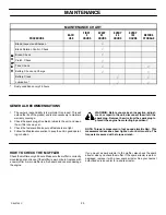
Your mower will require regular
maintenance and service. The
maintenance schedule depends on the
hours of use. Also, mowing conditions can
change the schedule. Check the
Instruction Book for more information.
Correct maintenance will help the mower
function safely.
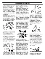
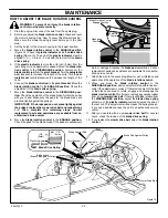
Do not service the
mower (except for the
carburetor adjustment)
while the engine is
running. Before you
service the unit, even
with the engine stopped,
always disconnect the
wire from the spark plug
to prevent the engine
from starting.
If you hit a large object during operation,
stop the engine. Remove the wire from the
spark plug. Carefully inspect the mower for
damage. Before you start the engine
again, make the necessary repairs. If you
feel new or excessive vibration,
immediately stop the engine and check for
the problem. Vibration can be a warning of
a problem. Keep all nuts, bolts and screws
tight.
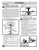
The blade is the most dangerous part of
the mower. Frequently check the blade and
the blade mounting fasteners. Keep the
fasteners tight. If the blade hits a solid
object, stop the engine. Remove the wire
from the spark plug. Check for a blade that
is bent, cracked or for other damages.
Before you start the engine, replace a
damaged blade(s). For safety, replace the
blade every two years.
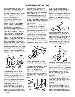
A sharp blade decreases the workload on
the engine and more evenly cuts grass.
Frequently sharpen the blade for a better
looking cut. Use the left side of the mower
housing to trim near an object.
A grass bagger is a good accessory for
your mower. For best performance and
safety, make sure the grass bagger is
approved for use with your mower. Follow
the assembly and operation instructions
included with the grass bagger.
Some grass baggers require a special
blade for best performance. Before you
attach, check, or empty the grass bagger,
always stop the engine. Before each use of
the grass bagger, check for cracks, wear or
deterioration. Before you use the grass
bagger, replace a damaged part with a
replacement part approved by the factory.
For you to have a good green lawn, follow
the mowing procedures below. Do not cut
the grass too short. If you cut the grass too
short you can cause the grass to become
yellow or make the lawn look brown. Use a
lower height of cut in cool months when
the grass is thicker. Raise the height of cut
in hot dry periods. If you cut the grass with
a blade that is not sharp or at a slow
engine speed you can damage the grass.
Move the throttle control to the FAST
position when mowing and using the grass
bagger. Also, use a slower ground speed
when using the grass bagger.
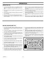
If you change the direction or pattern of cut
slightly every time you mow will make the
grass grow stronger and thicker. Do not
add oil or gasoline to the mower while on
the lawn. Spilled oil or gasoline can kill the
grass. In high or thick grass, do not try to
cut all the grass the first time. Raise the
height of cut on the first cutting and lower
the height for the next cutting. Another way
is to cut only part of the width of the mower
and decrease your ground speed (not the
engine) to move more slowly so that the
mower can discharge the grass as it
moves forward.
Understand the controls and how they
work. Learn the ground speed(s) of your
mower. Check the stopping distance
required at different travel speeds. Check
the turning radius of the mower. The
controls on your riding mower are different
from an automobile. The throttle is
operated by hand and holds the engine
speed constant until it is changed. The
location of the shift lever and the shift
pattern is different from that of an
automobile. Also, the brake and clutch
systems are different. Remember the
procedures to follow in an emergency.
Remember, turning off the engine ignition
switch will stop the blade and the drive
mechanism. If the traction of the wheels is
lost or does not feel safe, disengage all
systems and stop the engine. Dismount
from the mower. Push the unit to a safe
place before you begin mowing again.
Your unit has an electrical system that
includes an operator presence switch in
the seat. The operator presence switch
detects if the operator is sitting on the seat.
The engine will stop if the operator leaves
the seat when the blade engagement
control is engaged. This operator presence
switch is a safety device only. It must not
regularly be used to stop the engine or the
blade. There are other control systems on
the mower for this purpose. Always keep
the operator presence switch and other
safety devices and controls in place and
operating for your protection.
Remember, your mower is a tool that can
be dangerous if it is not correctly used.
Follow the instructions in this Instruction
Book. Safe and careful use of the mower
will give you many safe hours of problem
free use.