


en
17
7101898
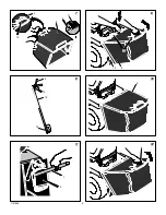
How To Check And Adjust The Drive
Brake
(Figure 24)
Completely push the clutch/brake pedal forward.
Set the parking brake. Move the shift lever to the
neutral (N) position. Push the unit. If the rear
wheels rotate, adjust or replace the brake pads.
Adjust the
drive brake (1)
as follows.
1. The location of the
drive brake (1)
is on the
right side of the
gearbox (3).
2. Make sure the parking brake is set and the
shift lever is in neutral (N). Turn the
hex nut
(2)
in a clockwise direction until the rear
wheels do not turn when the unit is pushed
forward.
3. Release the parking brake and push the unit.
If the unit does not roll, turn the
hex nut (2)
in a counterclockwise direction until the unit
rolls.
4. Set the parking brake. Push the unit. If the
rear wheels do not turn, the
drive brake (1)
is correctly adjusted. Release the parking
brake.
WARNING: If you cannot correctly
adjust the drive brake, replace the
brake pads. Correct replacement
parts and assistance are available from an
authorized service center.
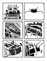
How To Remove The Battery
(Figure 4
)
To charge or clean the
battery (1)
, remove the
battery (1)
from the unit as follows.
WARNING: To prevent sparks, dis-
connect the black battery cable (8)
from the negative (--) terminal be-
fore you disconnect the red cable (5).
WARNING: The battery contains
sulphuric acid which is harmful to
the skin, eyes and clothing. If the
acid gets on the body or clothing, wash
with water.
1. Disconnect the
black cable (8)
from the
negative (--) terminal.
2. Disconnect the
red cable (5)
from the
posi-
tive (+) terminal (4).
3. Lift the
battery tray (3)
and the
battery (1)
out of the unit.
How To Charge The Battery
(Figure 4)
WARNING: When you charge the
battery, do not smoke. Keep the
battery away from any sparks. The
fumes from the battery acid can cause an
explosion.
1. Before you charge the
battery (1)
, remove
the
battery (1)
.
2. To charge the
battery (1)
, use a 12 volt bat-
tery charger. Charge at a rate of 6 amps for 1
hour.
3. Install the
battery (1).
WARNING: To prevent sparks,
fasten the red cable to the positive
(+) terminal before you connect the
black cable.
4. Fasten the
red cable (5)
to the
positive (+)
terminal (4)
with the fasteners as shown.
5. Fasten the
black cable (8)
to the negative
(--) terminal with the fasteners as shown.
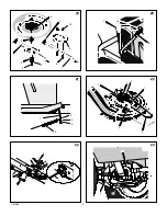
How To Level The Mower Housing
(Figure 25 and Figure 26)
If the mower housing is level, the blade will cut
easier and the lawn will look better.
WARNING: Before you make an in-
spection, adjustment, or repair to
the unit, disconnect the wire to the
spark plug. Remove the spark plug wire to
prevent the engine from starting by acci-
dent
1. Make sure the unit is on a hard flat surface.
2. Check the air pressure in the tires. If the air
pressure is incorrect, the mower housing will
not cut level. Make sure the tires are inflated
to: Front Tires 0,97 BAR (14 PSI), Rear
Tires 0,69 BAR (10 PSI).
3.
(Figure 25)
Move the
lift lever (1)
to the
lowest position (2)
.
WARNING: The lift lever (3) is
spring loaded. Make sure the lift
lever (1) is locked in the lowest
position (2).
4.
(Figure 26)
Loosen the left and right
ad-
juster knobs (1)
. Push down on each side of
the mower housing. Make sure both sides of
the mower housing are setting on a flat sur-
face. Also, make sure the
lift links (2)
are
loose and can easily move up or down.
5. Push down on the
adjuster knobs (1)
and
the
lift links (2).
Tighten the left and right
adjuster knobs (1)
. Make sure the
adjuster
knobs (1)
are tight. If necessary, use a
wrench to tighten the
adjuster knobs (1).
6.
(Figure 25)
Raise the
lift lever (1).
7. Mow for a short distance. If the height of cut
is not level, repeat the above steps.
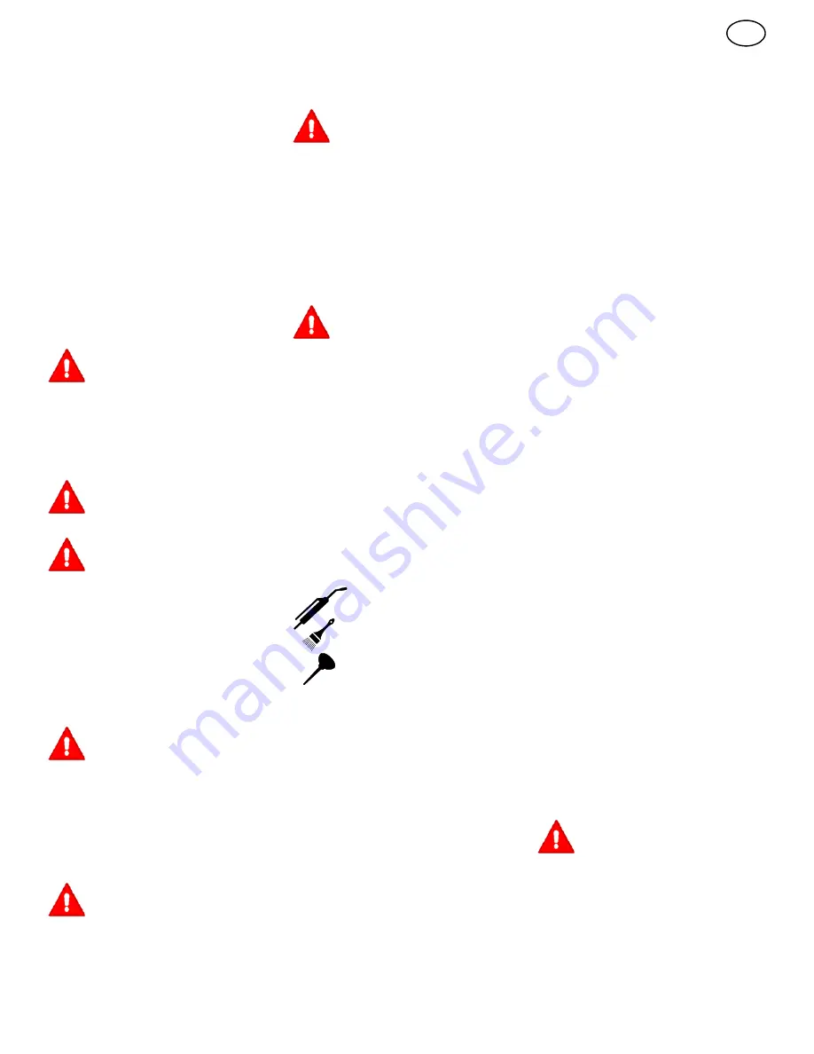
Where To Lubricate
(Figure 27)
Lubricate the areas shown
with engine oil.
Apply grease with a brush to
the areas shown.
Models with grease fittings:
Lubricate with grease gun.
NOTE: Apply grease to the steering gear as-
sembly.
CAUTION: If the unit is operated in dry areas
that have sand, use a dry graphite spray to
lubricate the unit.
Check The Tires
Check the air pressure in the tires. Tires with too
much air pressure will cause the unit to ride
rough. Also, the wrong air pressure will keep the
mower housing from cutting level. The correct
air pressure is: Front Tires 0,97 BAR (14 PSI),
Rear Tires 0,69 BAR (10 PSI).
How To Replace The Motion Drive Belt
1. Remove the mower housing. See the instruc-
tions on “How To Remove The Mower Hous-
ing”.
2. Completely push the pedal forward and en-
gage the parking brake.
3.
(Figure 28)
Remove the
idler pulley (1)
.
4.
(Figure 29)
To access the
belt guides (1)
,
remove the battery and battery tray. See
“How To Remove The Battery”.
5. Loosen the
belt guides (1)
at the
drive
pulley (2).
6.
(Figure 28)
Remove the
motion drive belt
(3)
from the
drive pulley (4).
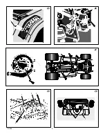
7.
(Figure 30)
Remove the
adjuster nut (2)
from the
shifter bracket (3).
Pull the motion
drive belt over the
shifter bracket (3)
.
8.
(Figure 31)
To remove the
motion drive belt
(1)
from the
stack pulley (2)
, pull the front
end of the belt under the
stack pulley (2)
and then back between the stack pulley and
the
steering plate (3)
.
9.
(Figure 32)
Remove the
access panel (1).
10.Remove the two
screws (4)
that attach the
steering shaft assembly (2).
Raise the
steering wheel and
steering shaft assembly
(2)
. Pull the
motion drive belt (3)
under the
steering shaft assembly (2)
.
11. Remove the motion drive belt. A correct re-
placement part or assistance is available
from an authorized service center in your
area.
12.To install the motion drive belt, reverse the
above steps.
13.
(Figure 33)
Check the routing of the
motion
drive belt (1)
. Make sure the motion drive
belt is installed correctly on the
idler pulley
(2)
. Make sure the
steering shaft assembly
(3)
is inside the
motion drive belt (1)
.
How To Replace The Mower Drive Belt
(Figure 22)
1. Remove the mower housing. See the instruc-
tions on “How To Remove The Mower Hous-
ing”.
2. Pull the
belt retainer (1)
away from the
idler
pulley (2)
and remove the
mower drive belt
(3).
3. Pull the
belt guide (4)
and the
brake as-
sembly (7)
away from the
mandrel pulley
(5)
and remove the
mower drive belt (3)
. A
correct replacement part or assistance is
available from an authorized service center
in your area.
4. To install the mower drive belt, reverse the
above steps.
5. Before you mow, check the blade rotation
control. See the instructions on “How to Ad-
just The Blade Rotation Control”.
How To Remove The Mower Housing
(Figure 34)
1. Move the
blade rotation control (1)
to the
DISENGAGE position.
2. Move the
lift lever (2)
to the lowest position.
WARNING: The lift lever (2) is
spring loaded. Make sure the lift
lever (2) is locked in the lowest
position.
3. Remove the hair pins and the washers from
the
adjuster arms (3)
. See illustrations “C”
and “D”.
4. Remove the hair pins and washers from the
suspension links (4)
. See illustrations “A”
and “B”.
5. Disconnect the
extension spring (5)
from
the
blade control rod (6)
. See illustration
“E”.
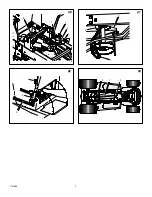
Summary of Contents for 312006x51A
Page 3: ...3 7101898 7 10 3 9 8 11 8 3 14 9 9 3 13 12 15 10 9 11 1 2 12 9 ...
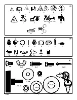
Page 4: ...4 7101898 3 6 1 2 4 5 7 13 1 2 14 2 1 15 1 2 16 3 7 8 5 17 18 4 3 6 9 ...
Page 6: ...6 7101898 1 2 25 1 2 26 1 2 27 1 2 28 3 4 1 29 2 ...
Page 7: ...7 7101898 1 2 3 4 5 30 3 2 1 31 6 1 2 3 4 32 1 3 2 33 ...
Page 8: ...8 7101898 2 3 3 4 4 5 6 7 8 9 1 1 34 1 ...
Page 112: ...lv 112 ...
Page 122: ...et 122 ...
Page 131: ...pl 131 ...
Page 140: ...140 ...
Page 141: ......