3. Board Design
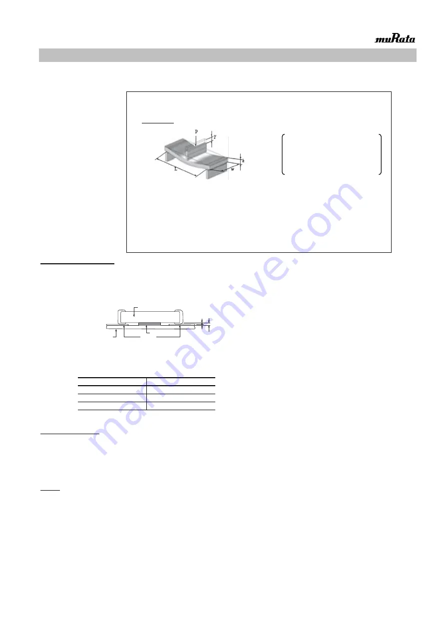
When designing the board, keep in mind that the amount of strain which occurs will increase depending on the size
and material of the board.
2.Adhesive Application
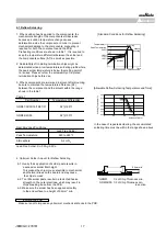
1. Thin or insufficient adhesive can cause the chips to loosen or become disconnected during flow soldering.
The amount of adhesive must be more than dimension c, shown in the drawing at right, to obtain the correct bonding
strength. The chip's electrode thickness and land thickness must also be taken into consideration.
2. Low viscosity adhesive can cause chips to slip after mounting. The adhesive must have a viscosity of
5000Pa • s (500ps) min. (at 25
℃
)
3. Adhesive Coverage
Size (L×W) (in mm)
Adhesive Coverage*
1.6 × 0.8
0.05mg min.
2.0 × 1.25
0.1mg min.
3.2 × 1.6
0.15mg min.
*Nominal Value
3.Adhesive Curing
1. Insufficient curing of the adhesive can cause chips to disconnect during flow soldering and causes
deterioration in the insulation resistance between the outer electrodes due to moisture absorption.
Control curing temperature and time in order to prevent insufficient hardening.
4.Flux
1. An excessive amount of flux generates a large quantity of flux gas, which can cause a deterioration of solderability,
so apply flux thinly and evenly throughout. (A foaming system is generally used for flow solderring.)
2. Flux containing too high a percentage of halide may cause corrosion of the outer electrodes unless there is
sufficient cleaning. Use flux with a halide content of 0.1% max.
3. Do not use strong acidic flux.
4. Do not use water-soluble flux.*
(*Water-soluble flux can be defined as non-rosin type flux including wash-type flux and non-wash-type flux.)
Notice
Land
Adhesive
Board
Chip Capacitor
a
b
c
a=20 to
70μm
b=30 to
35μm
c=50 to 105
μm
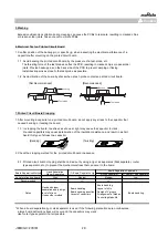
Relationship with amount of strain to the board thickness, length, width, etc.]
ε=
3PL
2
Ewh
2
Relationship between load and strain
When the load is constant, the following relationship can be established.
· As the distance between the supporting points (L) increases,the amount of strain also increases.
→Reduce the distance between the supporting points.
· As the elastic modulus (E) decreases, the amount of strain increases.
→Increase the elastic modulus.
·
As the board width (w) decreases, the amount of strain increases.
→Increase the width of the board.
·
As the board thickness (h) decreases, the amount of strain increases.
→Increase the thickness of the board.
Since the board thickness is squared, the effect on the amount of strain becomes even greater.
ε
:
Strain on center of board (
μst)
L
:
Distance between supporting points (mm)
w
:
Board width (mm)
h
:
Board thickness (mm)
E
:
Elastic modulus of board (N/m
2
=Pa)
Y
:
Deflection (mm)
P
:
Load (N)
JEMCGC-2701W
27


