


Temperature
Compensating Type
High Dielectric
Constant Type
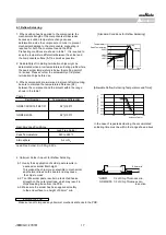
16 Humidity
The measured and observed characteristics should satisfy
Solder the capacitor on the test jig(glass epoxy board) shown in Fig.3
(Steady
State)
the specifications in the following table.
using an eutectic solder.
Appearance
No defects or abnormalities.
Capacitance
Within
±
5% or
±
0.5pF
R6,R7,R9,C8,L8 : Within
±
12.5%
Set the capacitor at 40±2
℃
and in 90 to 95% humidity for 500±12 hours.
Change
(Whichever is larger)
E4,F5 : Within
±
30%
Remove and set for 24±2 hours at room temperature, then measure.
Q/D.F.
30pF and over: Q
≧
350
[
R6,R7,R9,C8,L8
]
10pF and over
W.V.:100V : 0.05max.( C
<
0.068
m
F)
30pF and below: Q
≧
275+5C/2
: 0.075max.(C
≧
0.068
m
F)
10pF and below: Q
≧
200+10C
W.V.:50V/25V : 0.05max.
W.V.:16V/10V : 0.05max.
C:Nominal Capacitance(pF)
W.V.:6.3V/4V : 0.075max.(C
<
3.3
m
F)
: 0.125max.(C
≧
3.3
m
F)
[R9]
W.V.:50V : 0.075max.
[E4]
W.V.:25V : 0.05max.
[F5]
W.V.:25Vmin : 0.075max. (C
<
0.1
m
F)
: 0.125max. (C
≧
0.1
m
F)
W.V.:16V/10V : 0.15max.
W.V.:6.3V : 0.2max.
I.R.
More than 1,000M
W
or 50
W
·F(Whichever is smaller)
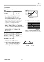
17 Humidity Load
The measured and observed characteristics should satisfy
Solder the capacitor on the test jig(glass epoxy board) shown in Fig.3
the specifications in the following table.
using an eutectic solder.
Appearance
No defects or abnormalities.
Capacitance
Within
±
7.5% or
±
0.75pF
R6,R7,R9,C8,L8 : Within
±
12.5%
Apply the rated voltage at 40±2
℃
and 90 to 95% humidity for
Change
(Whichever is larger)
E4 : Within
±
30%
500±12 hours. Remove and set for 24±2 hours at room temperature,
F5 : Within
±
30%(W.V.>10V)
then measure. The charge/discharge current is less than 50mA.
F5 : 30/-40%(W.V.
≦
10V)
Q/D.F.
30pF and over: Q
≧
200
[
R6,R7,R9,C8,L8
]
·Initial measurement for F5/10Vmax.
30pF and below: Q
≧
100+10C/3
W.V.:100V : 0.05max.( C
<
0.068
m
F)
Apply the rated DC voltage for 1 hour at 40±2°C.
: 0.075max.(C
≧
0.068
m
F)
Remove and set for 24±2 hours at room temperature.
C:Nominal Capacitance(pF)
W.V.:50V/25V : 0.05max.
Perform initial measurement.
W.V.:16V/10V : 0.05max.
W.V.:6.3V/4V : 0.075max.(C
<
3.3
m
F)
: 0.125max.(C
≧
3.3
m
F)
[R9]
W.V.:50V : 0.075max.
[E4]
W.V.:25V : 0.05max.
[F5]
W.V.:25Vmin : 0.075max. (C
<
0.1
m
F)
: 0.125max. (C
≧
0.1
m
F)
W.V.:16V/10V : 0.15max.
W.V.:6.3V : 0.2max.
I.R.
More than 500MΩ or 25Ω·F(Whichever is smaller)
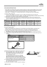
18 High Temperature
The measured and observed characteristics should satisfy
Solder the capacitor on the test jig(glass epoxy board) shown in Fig.3
Load
the specifications in the following table.
using an eutectic solder.
Appearance
No defects or abnormalities.
Capacitance
Within
±
3% or
±
0.3pF
R6,R7,R9,C8,L8:Within
±
12.5%
Apply 100% of the rated voltage at the maximum operating
Change
(Whichever is larger)
E4 :Within
±
30%
temperature ±3
℃
for 1000±12 hours.
F5 :Within
±
30%(Cap<1.0
m
F)
Set for 24±2 hours at room temperature, then measure.
F5 :30/-40%(Cap
≧
1.0
m
F)
The charge/discharge current is less than 50mA.
Q/D.F.
30pF and over: Q
≧
350
[
R6,R7,R9,C8,L8
]
10pF and over
W.V.:100V : 0.05max.( C
<
0.068
m
F)
·Initial measurement for high dielectric constant type.
30pF and below: Q
≧
275+5C/2
: 0.075max.(C
≧
0.068
m
F)
Apply 100% of the rated DC voltage at the maximum operating
10pF and below: Q
≧
200+10C
W.V.:50V/25V : 0.05max.
temperature ±3°C for one hour.
W.V.:16V/10V : 0.05max.
Remove and set for 24±2 hours at room temperature.
C:Nominal Capacitance (pF)
W.V.:6.3V/4V : 0.075max.(C
<
3.3
m
F)
Perform initial measurement.
: 0.125max.(C
≧
3.3
m
F)
[R9]
W.V.:50V : 0.075max.
[E4]
W.V.:25V : 0.05max.
[F5]
W.V.:25Vmin : 0.075max. (C
<
0.1
m
F)
: 0.125max. (C
≧
0.1
m
F)
W.V.:16V/10V : 0.15max.
W.V.:6.3V : 0.2max.
I.R.
More than 1,000M
W
or 50
W
·F(Whichever is smaller)
■
SPECIFICATIONS AND TEST METHODS
No
Item
Specification
Test Method
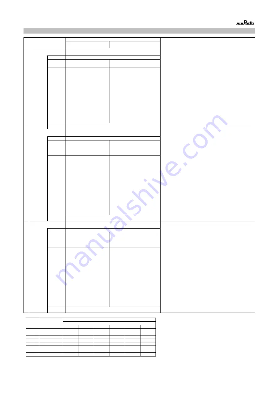
Table A-1
Char.
Nominal
Values
(ppm/
C) *
Capacitance Change from 25
C (%)
-55
-30
-10
Max.
Min.
Max.
Min.
Max.
Min.
5C
0
±
30
0.58
-0.24
0.40
-0.17
0.25
-0.11
6C
0
±
60
0.87
-0.48
0.59
-0.33
0.38
-0.21
6P
-150
±
60
2.33
0.72
1.61
0.50
1.02
0.32
6R
-220
±
60
3.02
1.28
2.08
0.88
1.32
0.56
6S
-330
±
60
4.09
2.16
2.81
1.49
1.79
0.95
6T
-470
±
60
5.46
3.28
3.75
2.26
2.39
1.44
7U
-750
±
120
8.78
5.04
6.04
3.47
3.84
2.21
1X
+350
~
-1000
-
-
-
-
-
-
* Nominal values denote the temperature coefficient within a range of 25
C to 125
C(for
C)/ 85
C(for other TC).
JEMCGS-00074C
4


