


6. Next press the
Start
button using the default 1 second
Refresh Delay
.
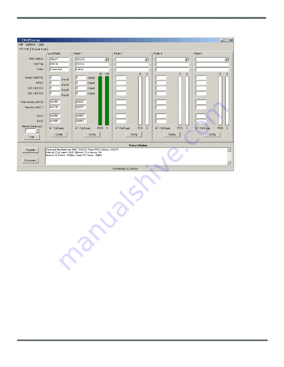
Figure 8.6.4
7. The Demo will display data on the
Remote
in the
Radio 1
column, including bar graphs of
RSSI
(signal strength) and
percent
packet success rate, as shown in Figure 8.6.4. Adjusting the pot on the
Remote
can be observed in the
Potentiometer (ADC0)
data. You can change the
Refresh
setting from the drop down menu at the bottom left. Adjusting
the pot on the base can be observed in the
Potentiometer (ADC0)
data in the
Local Radio
column.
If any difficulty is encountered in setting up the DNT24DK development kit, contact MURATA’s module technical support
group. The phone number is +1.678.684.2000. Phone support is available from 8:30 AM to 5:30 PM US Eastern Time
Zone, Monday through Friday. The E-mail address is [email protected].
©2009-2014 by Murata Electronics N.A., Inc.
DNT24 Integration Guide R2.0 - 10/27/14
www.murata.com


