background image

201703  

P

art 2 - Component La

y

o

ut and R

e

frig

e

ran
t Cir

cuits 

2 Piping Diagrams 

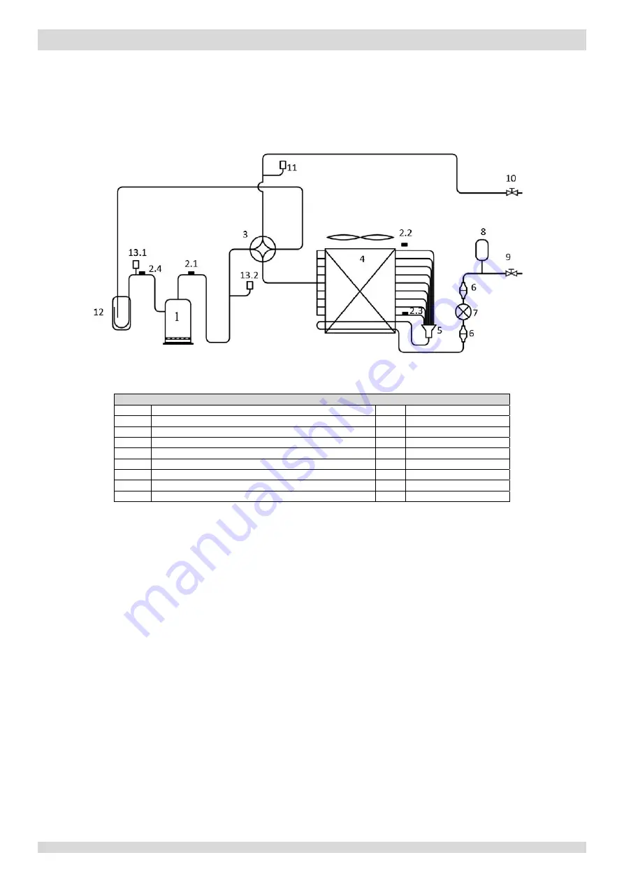
2.1 Outdoor Unit Piping   

Figure 2-2.1: 


piping diagram


Legend 

Compressor 

Electronic expansion valve 

2.1 

Discharge pipe temperature sensor 

Accumulator 

2.2 

Outdoor ambient temperature sensor 

Stop valve (liquid side) 

2.3 

Air side heat exchanger refrigerant outlet temperature sensor 

10 

Stop valve (gas side) 

2.4 

Suction pipe temperature sensor 

11 

Pressure sensor 

4-way valve 

12 

Separator 

Air side heat exchanger 

13.1 

Low pressure switch 

Distributor 

13.2 

High pressure switch 

Filter 


Key components: 

1.

Accumulator:


Stores liquid refrigerant and oil to protect compressor from liquid hammering. 

2.

Electronic expansion valve (EXV):


Controls refrigerant flow and reduces refrigerant pressure. 

3.

Four-way valve: 


Controls refrigerant flow direction. Closed in cooling mode and open in heating mode. When closed, the air side heat 

exchanger functions as a condenser and water side heat exchanger functions as an evaporator; when open, the air 

side heat exchanger functions as an evaporator and water side heat exchanger function as a condenser. 

4.

High and low pressure switches:   

Regulate refrigerant system pressure. When refrigerant system pressure rises above the upper limit or falls below the 

lower limit, the high or low pressure switches turn off, stopping the compressor.   

5.

Separator:


Separates liquid refrigerant from gas refrigerant to protect compressor from liquid hammering. 


Models 4 to 8kW

MUNDOCLIMA AEROTHERM V17 - BIBLOC

Summary of Contents for Aerotherm V17 Series

Page 1: ...ERM V17 Service Manual English www mundoclima com SO30160 to SO30172 Thank you very much for purchasing our product Before using your unit please read this manual carefully and keep it for future refe...

Page 2: ...201703 1 CONTENTS CONTENTS Part 1 General Information 3 Part 2 Component Layout and Refrigerant Circuits 5 Part 3 Control 13 Part 4 Diagnosis and Troubleshooting 27 MUNDOCLIMA AEROTHERM V17 BIBLOC...

Page 3: ...2 201703 MUNDOCLIMA AEROTHERM V17 BIBLOC...

Page 4: ...201703 3 Part 1 General Information Part 1 General Information 1 Unit Capacities 4 2 External Appearance 5 MUNDOCLIMA AEROTHERM V17 BIBLOC...

Page 5: ...14kW 16kW 1 2 Hydronic Box Capacities Table 1 2 1 Capacity range Capacity 8kW 16kW 16kW Model Compatible OU model BIBLOC V17 3Ph BIBLOC V17 1Ph SO30160 SO30161 SO30162 SO30163 SO30164 SO30165 SO30167...

Page 6: ...al Information 2 External Appearance 2 1 Outdoor Unit Appearance Table 1 2 1 Outdoor unit appearance 4 6kW 8kW 10 12 14 16kW 2 2 Hydronic Box Appearance Table 1 2 1 Hydronic box appearance MUNDOCLIMA...

Page 7: ...2 Component Layout and Refrigerant Circuits Part 2 Component Layout and Refrigerant Circuits 1 Layout of Functional Components 6 2 Piping Diagrams 9 3 Refrigerant Flow Diagrams 12 MUNDOCLIMA AEROTHER...

Page 8: ...Electronic expansion valve Gas side stop valve Liquid side stop valve Figure 2 1 2 front view DC inverter compressor Accumulator Air side heat exchanger Fan motor Separator Pressure sensor High press...

Page 9: ...alve Liquid side stop valve Figure 2 1 5 front view Air side heat exchanger Upper fan motor Lower fan motor Electronic expansion valve DC inverter compressor Accumulator Electric control box Pressure...

Page 10: ...ox Layout Figure 2 1 6 oblique view Electric control box Air purge valve Expansion vessel Water pump Water side heat exchanger Manometer Water flow switch Safety valve Backup electric heater MUNDOCLIM...

Page 11: ...ssor from liquid hammering 2 Electronic expansion valve EXV Controls refrigerant flow and reduces refrigerant pressure 3 Four way valve Controls refrigerant flow direction Closed in cooling mode and o...

Page 12: ...ction Closed in cooling mode and open in heating mode When closed the air side heat exchanger functions as a condenser and water side heat exchanger functions as an evaporator when open the air side h...

Page 13: ...n electric heater for water side heat exchanger 9 Manometer 14 2 Anti frozen electric heater for water inlet pipe 10 Safety valve Key components 1 Air purge valve Automatically removes air from the wa...

Page 14: ...and domestic hot water operation Figure 2 3 1 Refrigerant flow during heating or domestic hot water operation Cooling and defrosting operation Figure 2 3 2 Refrigerant flow during cooling and defrosti...

Page 15: ...Control 1 Stop Operation 14 2 Standby Control 14 3 Startup Control 15 4 Normal Operation Control 17 5 Protection Control 19 6 Special Control 22 7 Role of Temperature Sensors in Control Functions 24...

Page 16: ...ixing with compressor oil when the compressors are stopped The crankcase heater is controlled according to outdoor ambient temperature and the compressor on off state When the outdoor ambient temperat...

Page 17: ...ms until the target rotation speed is reached Refer to Figures 3 4 1 3 4 2 and 3 4 3 Figure 3 4 1 Compressor startup program 1 2 when ambient temperature is above 4 C 38rps Target rotation speed Compr...

Page 18: ...0 fully closed to 480 fully open controlled according to outdoor ambient temperature discharge temperature and suction superheat Four way valve ST On Notes 1 Refer to Figure 3 4 1 Figure 3 4 2 and Fi...

Page 19: ...pen controlled according to discharge temperature suction superheat and compressor speed Four way valve ST Off 4 2 Compressor Output Control The compressor rotation speed is controlled according to th...

Page 20: ...r 6 minutes have elapsed the EXV is then controlled according to suction superheat discharge temperature and compressor speed When the outdoor unit is in standby y The EXV is at position 304 steps Whe...

Page 21: ...stem displays P0 protection and the unit stops running When the suction pressure rises above 0 3MPa the compressor enters re start control 5 3 Discharge Temperature Protection Control This control pro...

Page 22: ...stops running When the compressor current drops below Currentmax the compressor enters re start control 5 5 Voltage Protection Control This control protects the M Thermal Split from abnormally high o...

Page 23: ...g After 3 minutes the unit restarts automatically When H6 protection occurs 10 times in 120 minutes the HH error is displayed When an HH error occurs a manual system restart is required before the sys...

Page 24: ...DC fan motor FAN_DOWN Electronic expansion valve EXV 304 steps Four way valve ST Off Tables 3 7 2 show component control during oil return operation in heating and DHW modes Table 3 7 2 Outdoor unit c...

Page 25: ...force cooling operation rotation speed DC fan motor Upper DC fan motor FAN1 FAN_UP Runs at force cooling operation speed Lower DC fan motor FAN_DOWN Electronic expansion valve EXV 304 steps Four way v...

Page 26: ...ontrol Functions Figure 3 7 1 Location of the temperature sensors on M Thermal Split systems Notes 1 The names and functions of the temperature sensors labelled 1 to 12 in this figure are detailed in...

Page 27: ...er water outlet temperature sensor Tw_out Heating Compressor output 5 and on off control 6 Freeze prevention control 10 Cooling DHW 9 Backup electric heater water outlet temperature sensor T1 Heating...

Page 28: ...26 201703 MUNDOCLIMA AEROTHERM V17 BIBLOC...

Page 29: ...t 4 Diagnosis and Troubleshooting Part 4 Diagnosis and Troubleshooting 1 Electric Control Box Layout 28 2 PCBs 31 3 Error Code Table 45 4 Troubleshooting 47 5 Appendix to Part 4 98 MUNDOCLIMA AEROTHER...

Page 30: ...Communication terminal blocks Main PCB Inverter module Capacitor Transformer Figure 4 1 2 electric control box Figure 4 1 3 side view Transformer Main PCB Inverter module Capacitors Communication term...

Page 31: ...nication terminal blocks Power supply terminals Figure 4 1 5 electric control boxfront view bottom layer Figure 4 1 6 electric control box side view Capacitors Inverter module Filter board Three phase...

Page 32: ...c heater circuit breaker Transformer Lighting filter board Power supply terminals Communication terminal blocks Figure 4 1 7 3Ph electric control box Main PCB Backup electric heater contactors Tank el...

Page 33: ...o the main PCB all models have an inverter module and the three phase models also have a filter board The locations of each PCB in the outdoor unit electric control boxes are shown in Figures 4 1 1 to...

Page 34: ...N8 Discharge pipe temperature sensor Tp connection 9 CN13 Yellow High pressure switch connection Red Low pressure switch connection 10 CN11 Suction pipe temperature sensor Th connection 11 CN14 Pressu...

Page 35: ...nnections to main PCB for refrigerant system 2 U V W Compressor connections 3 N IPM module input port N 4 P IPM module input port P 5 P1 Inductor power input 6 P5 Bridge rectifier input 7 P6 Bridge Re...

Page 36: ...igure 4 2 3 outdoor unit main PCB 1 Notes 1 Label descriptions are given in Table 4 2 3 Models 10 to 16kW 1Ph 20 19 18 25 17 16 23 22 21 9 10 15 26 14 13 12 1 2 3 4 5 6 7 8 24 11 MUNDOCLIMA AEROTHERM...

Page 37: ...o hydronic box main PCB 7 CN30 Reserved 8 CN22 Electronic expansion valve drive port 9 CN1 Power input L 10 CN2 Power input N 11 CN3 Power output port to bridge rectifier live wire 12 CN4 Power output...

Page 38: ...W Compressor connections 4 V 5 U 6 N_1 PFC module output port N 7 P_1 PFC module output port P 8 L_1 Power input port for PFC inductor 9 L_2 Power input port for PFC inductor 10 VIN N Input port N for...

Page 39: ...d Troubleshooting Figure 4 2 5 outdoor unit main PCB 1 Notes 1 Label descriptions are given in Table 4 2 5 10 11 1 8 2 9 3 4 5 6 24 7 13 12 14 15 16 17 18 19 21 20 22 23 25 26 Models 10 to 16kW 3Ph MU...

Page 40: ...port between hydronic box main PCB and outdoor unit main PCB 8 SW1 Force cool button 9 SW2 Check button 10 CN22 Port for electrical expansion value 11 CN41 Port for power supply 12 CN4 Power supply fo...

Page 41: ...inverter module Label in Figure 4 2 6 Code Content 1 CN4 15V port 2 CN1 MCU connection 3 W Compressor connections 4 V 5 U 6 P IPM module input port P 7 N IPM module input port N 8 CN2 Refrigerant sys...

Page 42: ...N Power supply N 5 GND_1 Ground wire 6 CN18 Power supply for load such as 4 way valve and crank heater of compressor 7 CN19 Power supply for refrigerant system main control board 8 L1 Power filtering...

Page 43: ...bleshooting 2 2 Hydronic Box PCB Figure 4 2 8 Hydronic box main PCB 1 Notes 1 Label descriptions are given in Table 4 2 8 28 1 8 7 6 5 4 3 2 11 9 10 12 13 14 23 24 25 26 27 15 17 18 16 19 20 21 22 29...

Page 44: ...uxiliary heat source water outlet temperature sensor T1B connection 11 CN16 Room temperature sensor Ta connection 12 SW4 Check button 13 S1 S2 DIP switches 14 CN34 Defrost connection 15 CN40 Anti free...

Page 45: ...t outlet temperature C Actual value value displayed 6 Outdoor ambient temperature C When no decimal point is displayed y Temperature is 9 C y Actual value value displayed When decimal point is display...

Page 46: ...Water side heat exchanger water outlet temperature C Actual value value displayed 12 Water side heat exchanger water inlet temperature C Actual value value displayed 13 Outdoor ambient temperature C...

Page 47: ...exchanger water inlet temperature sensor error User interface and hydronic box main PCB Sensor Tw_in EE Hydronic box EEPROM error User interface and hydronic box main PCB H0 Communication error betwe...

Page 48: ...PCB P6 Inverter module protection User interface Displayed on user interface when any of L0 L1 L2 L4 L5 L7 L8 or L9 occur L0 Inverter module protection Outdoor unit main PCB L1 DC bus low voltage prot...

Page 49: ...cordance with all applicable legislation all national local and other laws standards codes rules regulations and other legislation that apply in a given situation Power off the outdoor units before co...

Page 50: ...an E0 error occurs a manual system restart is required before the system can resume operation M Thermal Split stops running Error code is displayed on hydronic box main PCB and user interface Possibl...

Page 51: ...Water flow switch is damaged Yes Replace the water flow switch No Internal circulator pump fuse backup electric heater fuse or hydronic box main PCB fuse has blown3 Yes Replace the blown fuse No Repl...

Page 52: ...ly applies to 3 phase models M Thermal Split stops running Error code is displayed on outdoor unit main PCB and user interface Possible causes 4 3 3 Power supply phases not connected in correct sequen...

Page 53: ...phase sequence is inverted the compressor will operate inversely If the wiring connection of each outdoor unit is in A B C phase sequence and multiple units are connected the current difference betwe...

Page 54: ...ain PCB and user interface Possible causes 4 4 3 Communication wires between hydronic box and user interface not connected properly Communication wiring P Q E terminals misconnected Loosened wiring wi...

Page 55: ...s Ensure the communication wires and high voltage wires are separated No Communication wires are close to a source of electromagnetic radiation such as transformer or strong fluorescent lamp Yes Remov...

Page 56: ...efrigerant inlet liquid pipe temperature sensor error Ed indicates a water side heat exchanger water inlet temperature sensor error HA indicates a water side heat exchanger water outlet temperature se...

Page 57: ...on the hydronic box main PCB labeled 8 in Figure 4 2 8 in Part 4 2 2 Hydronic Box PCB Domestic hot water tank temperature sensor connection is port CN13 on the hydronic box main PCB labeled 9 in Figu...

Page 58: ...outdoor ambient temperature sensor error E9 indicates a suction pipe temperature sensor error EA indicates a discharge temperature sensor error M Thermal Split stops running Error code is displayed on...

Page 59: ...labeled 8 in Figure 4 2 1 and labelled 4 in Figures 4 2 3 and 4 2 5 in Part 4 2 1 Outdoor Unit PCBs Suction pipe temperature sensor connection is port CN11 on the models 4 to 8kW outdoor unit refriger...

Page 60: ...auses 4 7 3 Hydronic box main PCB EEPROM is not connected properly Hydronic box main PCB damaged Procedure 4 7 4 EE Hydronic box main PCB EEPROM1 is not connected properly Yes Ensure the EEPROM is con...

Page 61: ...is not connected properly Outdoor unit main PCB damaged Procedure 4 8 4 HF Outdoor unit EEPROM1 is not connected properly Yes Ensure the EEPROM is connected properly No Replace outdoor unit main PCB...

Page 62: ...rmal power supply No A transformer has malfunctioned2 Yes Replace the transformer No There is a source of electromagnetic radiation near the unit such as high frequency transmitter or other high stren...

Page 63: ...Yes Provide normal power supply No The transformer has malfunctioned2 Yes Replace the transformer No There is a source of electromagnetic radiation near the unit such as high frequency transmitter or...

Page 64: ...he system can resume operation The cause of an HH error should be addressed promptly in order to avoid system damage M Thermal Split stops running Error code is displayed on outdoor unit main PCB and...

Page 65: ...ace IPM module No Replace outdoor unit main PCB Notes 1 Refer to Figures 4 1 1 to 4 1 6 in Part 4 1 1 Outdoor Unit Electric Control Box Layout and to the M Thermal Split Engineering Data Book Part 2 5...

Page 66: ...rror code is displayed on outdoor unit main PCB and user interface Possible causes 4 12 3 Power supply voltage not within 10 of rated voltage or a phase is missing Outdoor unit powered on immediately...

Page 67: ...l box power supply terminals are loose Yes Ensure the wires are connected properly No Outdoor unit powered on immediately after being powered off Yes Power off the unit and wait for at least 3 minutes...

Page 68: ...tdoor unit main PCB is loose Yes Ensure the sensor is connected properly No High pressure sensor has short circuited or failed1 Yes Replace the sensor No Replace outdoor unit main PCB Notes 1 Measure...

Page 69: ...l operation resumes HP indicates P0 protection has occurred 3 times in 60 minutes When an HP error occurs a manual system restart is required before the system can resume operation Error code is displ...

Page 70: ...ent refrigerant An insufficiency of refrigerant causes compressor discharge temperature to be higher than normal discharge and suction pressures to be lower than normal and compressor current to be lo...

Page 71: ...Thermal Split stops running When the discharge pressure falls below 3 2MPa P1 is removed and normal operation resumes Error code is displayed on outdoor unit main PCB and user interface Possible caus...

Page 72: ...Part 4 2 1 Outdoor Unit PCBs Pressure sensor connection is port CN14 on the models 4 to 6kW refrigerant system main PCB labeled11 in Figure 4 2 1 in Part 4 2 1 Outdoor Unit PCBs port CN28 on the model...

Page 73: ...phase 10 to 16kW models 31A three phase models 15A the system displays P3 protection and M Thermal Split stops running When the current returns to the normal range P3 is removed and normal operation r...

Page 74: ...g circulator pumps and water flow switch for dirt blockages In cooling mode check air side heat exchanger fan s and air outlets for dirt blockages 2 High pressure side blockage causes discharge temper...

Page 75: ...es above 115 C the system displays P4 protection and M Thermal Split stops running When the discharge temperature falls below 83 C P4 is removed and normal operation resumes Error code is displayed on...

Page 76: ...onnection or pressure sensor connection on outdoor unit main PCB is loose4 Yes Ensure the pressure switch is connected properly No Pressure sensor has short circuited or failed5 Yes Replace the pressu...

Page 77: ...o 16kW 1Ph outdoor unit main PCB labeled 1 in Figure 4 2 3 in Part 4 2 1 Outdoor Unit PCBs and port CN6 on the models 10 to 16kW 3Ph outdoor unit main PCB labeled 6 in Figure 4 2 5 in Part 4 2 1 Outdo...

Page 78: ...ter inlet and water outlet temperatures protection M Thermal Split stops running Error code is displayed on hydronic box main PCB and user interface Possible causes 4 18 3 Temperature sensor not conne...

Page 79: ...otes 1 Water side heat exchanger water inlet temperature sensor and water side heat exchanger water outlet temperature sensor connections are port CN6 on the hydronic box main PCB labeled 8 in Figure...

Page 80: ...If a P6 error code is displayed on the user interface one of the following specific error codes is displayed on the outdoor unit main PCB L0 L1 L2 L4 L5 L7 L8 L9 Refer to Table 4 4 1 Table 4 4 1 Spec...

Page 81: ...ectifier Contactor is open the current across the PTC to charge capacitor after 5 seconds the contactor closed The capacitor output steady power supply for inverter module P N terminals In standby the...

Page 82: ...le to the correct compressor terminals as indicated by the labels on the compressor 2 Measure the resistance between each of U V and W and each of P and N on the inverter module All the resistances sh...

Page 83: ...eplace the inverter module3 Notes 1 Refer to Figure 4 4 1 2 Use clip on ammeter to measure the compressor current if the current is normal indicates the inverter module is failed if the current is abn...

Page 84: ...y of the resistances is close to zero the bridge rectifier has failed Method 2 dial a multimeter to the diode setting Put the red probe on the DC power output negative terminal terminal 5 and put the...

Page 85: ...amaged1 Yes Replace the inverter module2 Notes 1 If the fan motor is running and the DC voltage between terminals P and N on inverter module is not 380V the PFC is damaged 2 When replacing an inverter...

Page 86: ...differs from target frequency Specific error codes for P6 inverter module protection 4 20 4 If a P6 error code is displayed on the user interface one of the following specific error codes is displayed...

Page 87: ...nd then repeats L5 Zero speed protection Flashes 15 times and stops for 1 second then repeats L7 Phase sequence error Flashes 16 times and stops for 1 second then repeats L8 Compressor frequency varia...

Page 88: ...oor unit main PCB and inverter module is port CN201 on outdoor unit main PCB and port CN1 on inverter module 2 Measure the resistance between each of U V and W and each of P and N on the inverter modu...

Page 89: ...N terminal on the inverter module through the current sensor in the direction indicated by the arrow on the current sensor and end at the N terminal of capacitor Refer to Figure 4 4 5 Figure 4 4 5 DC...

Page 90: ...ire from the inverter module to the correct compressor terminals as indicated by the labels on the compressor 2 Measure the voltage between each of W W V V U U and GND when the unit is in standby The...

Page 91: ...ce the compressor No Replace the inverter module2 Notes 1 When replacing an inverter module a layer of thermally conductive silica gel should be painted on the IPM module on the reverse side of the in...

Page 92: ...L2 P N 15V wire on outdoor unit main PCB is not connected properly1 Yes Ensure P N 15V wire is connected properly No Voltage between N and 15 is abnormal2 Yes Check 15V circuit3 No DC voltage between...

Page 93: ...ch of terminals 1 2 and 3 should be around 0 378V If the voltage is 0 the bridge rectifier has failed Put the red probe on the DC power output positive terminal terminal 4 then put black probe onto ea...

Page 94: ...ires which connect the contactor with the outdoor unit main PCB If the voltage is 220V AC and the contactor is open the contactor has failed Condition 3 L4 error appears after the compressor has been...

Page 95: ...ed properly No Water side heat exchanger water outlet temperature sensor water inlet temperature sensor or backup electric heater outlet water temperature sensor has short circuited or failed3 Yes Rep...

Page 96: ...stem displays Pd protection and M Thermal Split stops running When the air side heat exchanger refrigerant outlet temperature returns drops below 52 C Pd is removed and normal operation resumes M Ther...

Page 97: ...r main PCB Notes 1 Air side heat exchanger refrigerant outlet temperature sensor and outdoor ambient temperature sensor connection port is CN9 on the outdoor unit main PCB labeled 7 in Figure 4 2 1 in...

Page 98: ...s higher than outlet temperature in heating mode M Thermal Split stops running Error code is displayed on hydronic box main PCB and user interface Possible causes 4 23 3 Temperature sensor not connect...

Page 99: ...ensor and water side heat exchanger water outlet temperature sensor connections are port CN6 on the hydronic box main PCB labeled 8 in Figure 4 2 8 in Part 4 2 2 Hydronic Box PCB 2 Measure sensor resi...

Page 100: ...96 8 56 37 32 7 295 72 1 537 112 0 4470 7 52 24 33 6 981 73 1 485 113 0 4348 6 49 32 34 6 684 74 1 435 114 0 4230 5 46 57 35 6 400 75 1 387 115 0 4116 4 44 00 36 6 131 76 1 341 116 0 4006 3 41 59 37 5...

Page 101: ...61 4 33 38 89 73 8 643 113 2 559 6 247 8 34 37 30 74 8 358 114 2 489 5 234 9 35 35 78 75 8 084 115 2 422 4 222 8 36 34 32 76 7 820 116 2 357 3 211 4 37 32 94 77 7 566 117 2 294 2 200 7 38 31 62 78 7 3...

Page 102: ...734 19 450 81 21 58 804 61 11 715 101 3 1777 18 425 59 22 56 209 62 11 302 102 3 0853 17 401 91 23 53 742 63 10 906 103 2 9960 16 379 69 24 51 396 64 10 526 104 2 9096 15 358 83 25 49 165 65 10 161 10...

Page 103: ...www mundoclima com ASK FOR MORE INFORMATION Phone 34 93 446 27 81 eMail info mundoclima com TECHNICAL ASSISTANCE Phone 34 93 652 53 57...

Reviews: