


Ducted Split Type Air-Conditioning
4
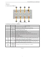
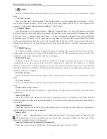
3 Buttons
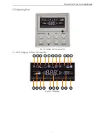
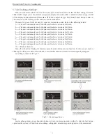
3.1 Silk Screen of Buttons
1
2
3
4
5
6
7
8
Fig. 3.1 Silk screen of buttons
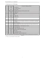
3.2 Instruction to Function of Buttons
No.
Description
Function of Button
1
Enter/cancel
(1) Function selection and canceling;
(2) Press it for 5s to enquiry the outdoor ambient temperature.
2
▲
(1) Running temperature setting of indoor unit, range :16~30
(2) Timer setting, range:0.5-24hr
(3) Switchover between quiet/auto quiet
6
▼
3
Fan
Setting of high/middle/low/auto fan speed
4
Mode
Setting of cooling/heating/fan/dry mode of indoor unit
5
Function
Switchover among the functions of air,/sleep/turbo/save/e-heater/blow /quiet
7
Timer
Timer setting
8
On/off
Turn on/off indoor unit
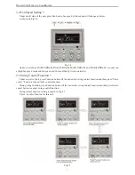
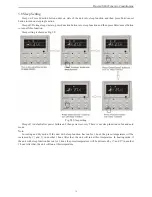
4 Mode
and
2 ▲
Memory
function
Press them for 5s under off state of the unit to enter/cancel memory function (If
memory is set, indoor unit after power failure and then power recovery will resume
original setting state .If not, indoor unit is defaulted to be off after power recovery.
Memory function is defaulted to be off before outgoing.)
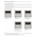
2 ▲
and
6 ▼
Lock
Upon startup of the unit without malfunction or under off state of the unit, press
them at the same time for 5s in to lock state. In this case, any other buttons won’t
respond the press. Repress them for 5s to quit lock state.
4 Mode
and
5 Function
Enquiry
and setting
of address
of wired
controller
Press them for 5s under unit off at the same time to set address.
Table 3.1
4 Installation of Wired Controller and Project Debugging
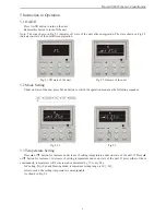
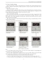
4.1 Installation of Wired Controller
Fig.4.1: Sketch for Installation of Wired Controller
No.
1
2
3
4
5
Description
Socket’s base box
installed in the
wall
Soleplate of
controller
Screw M4X25
Front panel of
controller
Screw ST2.2X6.5
Fig.4.1: Sketch for Installation of Wired Controller. Pay attention to the following items during installation
of wired controller:
1)
Cut off power supply of heavy-current wire embedded in mounting hole in the wall before installation. It
is prohibited to perform the whole procedure with electricity.
2) Pull out 4-core twisted pair line in mounting hole and then make it through the rectangle hole at the back
of controller’s soleplate.
3)
Joint the controller’s soleplate on wall face and then fix it in mounting hole with screws M4X25.
4) Insert the 4-core twisted pair through rectangle hole into controller’s slot and buckle the front panel and
soleplate of controller together.
5)
At last, fix the controller’s front panel and soleplate with screws ST2.2X6.5.
Caution:
During connection of wirings, pay special attention to the following items to avoid interference of
electromagnetism to unit and even failure of it.
1) To ensure normal communication of the unit, signal line and wiring (communication) of wired controller
should separate from power cord and indoor/outdoor connection lines. The distance between them should be
kept 20cm in min.
2) If the unit is installed at the place where there is interference of electromagnetism, signal line and wiring
(communication) of wired controller must be shielding twisted pair lines.
Summary of Contents for MUCH-20-H4
Page 36: ......
Page 37: ......
Page 38: ......
Page 43: ...Proven a 392 pl 2 08025 Barcelona Tel 93 446 27 80 Fax 93 456 90 32...