background image

MAYCO LS300G CONCRETE PUMP • OPERATION MANUAL — REV. #2 (09/09/19) — PAGE 53

TRAILER MAINTENANCE

Periodically check the actuator mounting fasteners for 

damage or loosening. Inspect the actuator for worn or 

damaged parts. As you are towing your trailer, be aware 

of any changes in braking quality. This could be an early 

warning of brake or actuator malfunction and requires 

immediate attention. Consult a certified brake specialist to 

make necessary adjustment or repairs

ADJUSTABLE CHANNEL

Your trailer may be equipped with an adjustable channel 

(Figure 58) that allows the coupler to be raised or lowered 

to a desired height. Periodically check the channel bolts 

for damage or loosening.

  WARNING

Failure to maintain proper fluid level in the actuator 

may result in loss of braking action which could cause 

severe property damage, injury or death.

Table 8. Hydraulic Brake Troubleshooting

Symptom

Possible Cause

Solution

No Brakes 

Brake line broken or kinked?

Repair or replace.

Weak Brakes or 

Brakes Pull to  

One Side

Brake lining glazed?

Reburnish or replace.

Trailer overloaded?

Correct weight.

Brake drums scored or 

grooved?

Machine or replace.

Tire pressure correct?

Inflate all tires equally.

Tires unmatched on the 

same axle?

Match tires.

Locking Brakes

Brake components loose, 

bent or broken?

Replace components.

Brake drums out-of-round?

Replace.

Noisy Brakes

System lubricated?

Lubricate.

Brake components correct?

Replace and correct.

Dragging 

Brakes

Brake lining thickness 

incorrect or not adjusted 

correctly?

Install new shoes and 

linings.

Enough brake fluid or correct 

fluid?

Replace rubber parts  

fill with DOT 4 fluid.

NOTICE

When replacing channel mounting hardware (nuts, 

bolts and washers), 

NEVER

 substitute substandard 

hardware. Pay close attention to 

bolt length

 and 

grade

ALWAYS

 use manufacturer’s recommended parts 

when replacing channel mounting hardware.

Figure 58. Adjustable Channel

Wheel Bearings

Wheel bearings (Figure 58) must be inspected and 

lubricated once a year or every 12,000 miles to ensure 

safe operation of your trailer.
If trailer wheel bearings are immersed in water, they must 

be replaced.

If the trailer has not been used for an extended amount 

of time, have the bearings inspected and packed more 

frequently, at least every six months and prior to use.
Follow the steps below to disassemble the wheel hub and 

service the wheel bearings. See Figure 59.

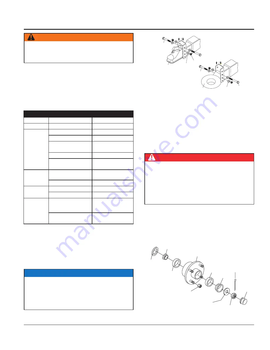
Figure 59. Wheel Hub Components

2" or 2-5/16" BALL

COUPLER

ADJUSTABLE

CHANNEL

5/8" FLAT

WASHER

5/8" X 11" X 5"

BOLT

5/8"

NYLOC

NUT

ADJUSTABLE

CHANNEL

5/8" FLAT

WASHER

5/8"

NYLOC

NUT

5/8" X 11" X 5"

BOLT

3" PINTLE EYE

RING

  DANGER

If trailer wheels are underwater for a long period of 

time, wheel bearings may fail. If this is the case, service 

wheel bearings immediately.
The possibility exists of the wheels falling off causing 

equipment damage and severe bodily harm or even 

death!

WHEEL

HUB

BEARING

CUP

BEARING

CUP

BEARING

BEARING

OIL

SEAL

SPINDLE

NUT

SPINDLE

WASHER

COTTER

PIN

DUST

CAP

LUG

NUT

Summary of Contents for MAYCO LS300G

Page 1: ...ACCOMPANY THE EQUIPMENT AT ALL TIMES Revision 2 09 09 19 SERIES MODEL LS300G CONCRETE PUMP ZENITH Z428 GASOLINE ENGINE To find the latest revision of this publication or associated parts manual visit...

Page 2: ...PAGE 2 MAYCO LS300G CONCRETE PUMP OPERATION MANUAL REV 2 09 09 19 PROPOSITION 65 WARNING...

Page 3: ...se cancer birth defects or other reproductive harm If you are unfamiliar with the risks associated with the particular process and or material being cut or the composition of the tool being used revie...

Page 4: ...2 25 Digital Control Panel Components 26 27 Engine Components 28 Inspection 29 31 Setup 32 Operation 33 38 Maintenance 39 51 Trailer Maintenance 52 54 Trailer Guidelines 55 69 Appendix Concrete Mix In...

Page 5: ...MAYCO LS300G CONCRETE PUMP OPERATION MANUAL REV 2 09 09 19 PAGE 5 NOTES...

Page 6: ...ER WARNING CAUTION or NOTICE SAFETY SYMBOLS DANGER Indicates a hazardous situation which if not avoided WILL result in DEATH or SERIOUS INJURY WARNING Indicates a hazardous situation which if not avoi...

Page 7: ...numbers of the nearest ambulance doctor and fire department This information will be invaluable in the case of an emergency PUMP SAFETY DANGER NEVER pump volatile explosive flammable or low flash poin...

Page 8: ...tness Also check towing tongue bolt lock nut and wheel lug nuts for wear Test the pump s emergency stop switch The purpose of this test is to shut down the engine in the event of an emergency Refer to...

Page 9: ...l fuel tank Tighten fuel cap until it clicks BATTERY SAFETY DANGER DO NOT drop the battery There is a possibility that the battery will explode DO NOT expose the battery to open flames sparks cigarett...

Page 10: ...and coupling of the towing vehicle are rated equal to or greater than the trailer gross vehicle weight rating ALWAYS inspect the hitch and coupling for wear NEVER tow a trailer with defective hitches...

Page 11: ...be sent to a recycling center Metal recycling involves the collection of metal from discarded products and its transformation into raw materials to use in manufacturing a new product Recyclers and man...

Page 12: ...428 Weight with fluids 3 955 lb 1 794 kg Tire Size ST 225 75 R15 Options Wireless Remote Control Hopper Screen Vibrator Volume output will vary depending on mix design slump line size used and job sit...

Page 13: ...RETE PUMP OPERATION MANUAL REV 2 09 09 19 PAGE 13 D C A E B Table 3 Pump Dimensions Reference Letter Dimensions in mm A 158 4 013 2 B 44 1 117 6 C 64 1 615 5 D 21 5 546 1 E 63 5 1 612 9 Figure 1 Dimen...

Page 14: ...ATION MANUAL REV 2 09 09 19 CHUTE UP CHUTE DOWN STOP START PUMP SPEED UP SLOW PUMP DOWN STOP PUMP LITTLE BIT ADD WATER 4 GALLONS ALL DONE CLEAN UP DRIVE IN BACK UP PULL FORWARD BACK IN IMPORTANT HAND...

Page 15: ...nuously coat the inside of the line with a lubricating seal of mortar There are four ways in which this seal can be lost 1 By pumping excessively wet mixes which do not have enough cohesion to hold to...

Page 16: ...on this Mayco Concrete Pump can be used to pump a large aggregate hard rock as follows Pea rock 1 2 minus pump with mixes being as low as 30 rock and 70 sand Reference Maintenance section for recommen...

Page 17: ...e as compared to hose When pumping vertically using all hose it is recommended not to go higher than 50 feet with hose The hose should be tied off at intervals of 10 feet if possible Special attention...

Page 18: ...blockage in the manifold when the pump is started 3 If it is necessary to wait 10 minutes or more for another load of concrete it is wise to start the pump and pump 6 or 8 strokes every 5 minutes to...

Page 19: ...d where it is and clear it before further pumping DO NOT increase the engine speed to clear the blockage Increasing the engine speed will only compound the problem If a blockage occurs in a hose walk...

Page 20: ...clamp and flip it up 4 Carefully knock the end of the hose away from the reducer GENERAL INFORMATION 5 Chip the concrete out of the reducer with the pry bar 6 Remove the reducer From the discharge end...

Page 21: ...RS PISTON CUP CONCRETE CYLINDERS SHUTTLE TUBE SLAVE OIL SHUTTLE TUBE MOTION A B Figure 4 Pumping Cycle 2 In the first cycle Figure 3 hydraulic pressure is applied to cylinder B causing the hydraulic p...

Page 22: ...PAGE 22 MAYCO LS300G CONCRETE PUMP OPERATION MANUAL REV 2 09 09 19 Figure 5 Pump Components 1 3 4 4 2 13 16 14 15 19 20 5 9 7 11 10 8 18 6 17 12 2 PUMP COMPONENTS...

Page 23: ...ponents section for component callouts 10 Inline Fuel Filter Replace or clean fuel filter as specified in the Maintenance section of this manual 11 OilFilter Preventsdirtandotherdebrisfromentering the...

Page 24: ...PAGE 24 MAYCO LS300G CONCRETE PUMP OPERATION MANUAL REV 2 09 09 19 PUMP COMPONENTS CONTINUED Figure 6 Pump Components Cont 33 41 41 34 35 36 25 30 31 23 24 40 21 37 38 26 32 39 29 27 28 22...

Page 25: ...newithoutanairfilter withadamaged air filter or with a filter in need of replacement will allow dirt to enter the engine causing rapid engine wear 31 Fuel Pump Delivers gasoline from the fuel tank to...

Page 26: ...ch controls the pumping function The leftmost position AUTOMATIC sets the pump to automatic cycling Set the switch to this position for normal pump operation The rightmost position JOG changes the pum...

Page 27: ...Screen 5 Displays the ON OFF electrical signal status of the various 12 volt solenoids Swing A circuit Main A circuit Main B circuit Screen 6 Displays the ON OFF electrical signal status for the Proxi...

Page 28: ...or Provides power to the electrical system Replace with only manufacturer s recommended replacement parts 5 Oil Pan Holds a maximum of 4 quarts 3 8 liters of engine oil 6 Starter Solenoid This engine...

Page 29: ...g any kind of maintenance service on the pump NOTICE ReferenceFigures5 6 and7forthelocationofanycontrol or component referenced in this section DANGER Handle fuel safely Motor fuels are highly flammab...

Page 30: ...ngine crankcase with lubricating oil through filler hole but DO NOT overfill 5 The oil listed in Table 4 is recommended to ensure better engine performance Use class CD or higher grade motor oil Hydra...

Page 31: ...ER LUBRICATION BOX SAE 30 WT MOTOR OIL INSPECTION CLEANINGTHE RADIATOR The engine may overheat if the radiator fins become overloaded with dust or debris Periodically clean the radiator fins with comp...

Page 32: ...le tee bolt eye and then pull the handle tee to release the stabilizer jack Figure 18 Rear Stabilizer Jack WARNING NEVER place feet under jack while operating ALWAYS retract rear stabilizer jacks prio...

Page 33: ...tch is in the closed position STOP engine will not start To start the engine make sure the emergency stop switch is in the OPEN position fully extended 4 Place the direction control switch to the FORW...

Page 34: ...ter 4 Position the first ready mix truck at the hopper Check the concrete DO NOT discharge concrete into hopper at this time 5 Place the direction control switch in the FORWARD position This will star...

Page 35: ...the OFF position Refer to Clearing Concrete Blockage Section THROTTLE ON STROKES 100 STROKES MIN 10 0 YDS HR 0 0 7 HYDRAULIC OIL TEMPERATURE 7 It is important that once the slurry procedure is complet...

Page 36: ...MO TE CO NT RO L FL OW DIR EC TIO N VO LU ME LOC AL FOR WA RD AUT OM ATIC JOG RES ET SET DEC REA SE INC REA SE SCR OLL JOG A CYL IND ER STR OKE JOG B REV ERS E CEN TER OFF REM OTE ST AR T REMOVE 2 SCR...

Page 37: ...p completely in an emergency PUMP ON OFF Starts and stops the forward pumping PUMP REV Momentarily pumps in reverse direction E STOP ON OFF PUMP REV VOLUME VOLUME PUMP ON OFF POWER LED NOTE OLDER MODE...

Page 38: ...digital panel Figure 37 Remote Control Cable Before the remote control cable can be used the pumping volume rate must be set 1 Start the pump as outlined in the pumping section of this manual 2 Place...

Page 39: ...y Acid Level X Check Fan Belt Condition X Check for Leaks X Check for Loosening of Parts X Replace Engine Oil and Filter 1 X Clean Air Filter X Check Fuel Filter Water Separator Bowl X Clean Unit Insi...

Page 40: ...run Ensure that the maintenance area is well ventilated Exhaust contains poisonous carbon monoxide gas that can cause unconsciousness and may result in DEATH CAUTION ALWAYS allow the engine to cool b...

Page 41: ...CE DO NOT run the engine with the air cleaner removed or without an element Checking Engine Oil Daily 1 When checking or adding oil place the machine so the engine is level 2 Pull the engine oil dipst...

Page 42: ...bricating oil filter head 2 Using an oil filter wrench Figure 42 remove engine oil filter Figure 42 Engine Oil Filter Removal 3 Coat the rubber seal gasket surface of oil filter Figure 42 with clean 1...

Page 43: ...iator cap until the unit has completely cooled The possibility of hot coolant exists which can cause severe burns Table 7 Anti Freeze OperatingTemperatures Vol Anti Freeze Freezing Point Boiling Point...

Page 44: ...pressure water or compressed air at greater than 28 psi 193 kPa or a wire brush to clean the radiator fins Radiator fins damage easily MAINTENANCE Fuel Filter Replace the engine in line fuel filter F...

Page 45: ...hock or Fire due to electric short circuit Disconnect battery cables before inspecting electrical system and never spark battery terminals to test for charge CAUTION Battery Safety Wear safety glasses...

Page 46: ...to some solid part of the mixer truck to prevent hook from jumping off of the drum Run the pump at 6 strokes per minute maximum speed NOTICE NEVER use muriatic acid to clean the pump Acid will dissolv...

Page 47: ...from the bottom of the box drain and clean the lubrication box Cleaning the Lubrication Box 1 Remove the top cover and the drain plug Figure 51 located at the bottom of the box and fully drain the in...

Page 48: ...urfaces it is time for replacement Due to the motion of the shuttle tube the cutting ring experiences a quicker rate of wear as opposed to the wear plate The wear ring typically requires replacement t...

Page 49: ...ear of the face plate Install over alignment studs and into concrete cylinders NOTICE Felt ring must be saturated with 30 wt oil prior to installation 13 Insert one 3 8 16 3 bolt into the open bolt ho...

Page 50: ...gine is turned on PressureTest 1 To determine the pressure of the hydraulic system set the cylinder stroke control switch Figure 53 to the JOG position Figure 53 Cylinder Stroke Control Switch JOG NOT...

Page 51: ...ting 3 Remove wheel and drum assemblies and spray a good anti corrosion compound CRC formula 5 56 under rubber boot on forward end of brake wheel cylinder Avoid spraying drum and brake lining 4 Grease...

Page 52: ...tool rotate the starwheel of the adjuster assembly to expand the brake shoes Adjust the brake shoes out until the pressure of the linings against the drum makes the wheel very difficult to turn Note Y...

Page 53: ...te Brake components correct Replace and correct Dragging Brakes Brake lining thickness incorrect or not adjusted correctly Install new shoes and linings Enough brake fluid or correct fluid Replace rub...

Page 54: ...The possibility exists of the trailer falling thus causing equipment damage and severe bodily harm even death DANGER When performing trailer inspection and maintenance activities you must jack up the...

Page 55: ...is that the passing distance with a trailer is 4 times the passing distance without the trailer Shift your automatic transmission into a lower gear for city driving ALWAYS use lower gears for climbin...

Page 56: ...your speed as road weather and lighting conditions deteriorate Always check for local trailer tow speed limits in your area WARNING Do not transport people on the trailer The transport of people puts...

Page 57: ...s well as the area to the rear of it WARNING Improper electrical connection between the tow vehicle and the trailer will result in inoperable lights and can lead to collision Before each tow check tha...

Page 58: ...weights of your tow vehicle without the trailer coupled Some of the trailer weight will be transferred from the trailer to the tow vehicle axles and an axle scale weighs all axles including the tow ve...

Page 59: ...r are discussed below Ball Hitch Coupler Pintel Eye Coupler BALL HITCH COUPLER A ball hitch coupler Figure C connects to a ball that is located on or under the rear bumper of tow vehicle This system o...

Page 60: ...ll WARNING A loose hitchball nut can result in uncoupling leading to death or serious injury Be sure the hitch ball is tight to the hitch before coupling the trailer the trailer tongue Wood or concret...

Page 61: ...h unless the hitch has holes or loops specifically for that purpose Cross chains underneath hitch and coupler with enough slack to permit turning and to hold tongue up if the trailer comes loose Break...

Page 62: ...intle eye coupler Figure G connects to a pintle hook hitch that is located on or under the rear bumper of the tow vehicle This system of coupling a trailer to a tow vehicle is sometimes referred to as...

Page 63: ...fail while towing and may result in death or serious injury Before coupling trailer inspect the pintle hitch hook for wear corrosion and cracks Replace worn or damaged pintle hitch hook CouplingTrail...

Page 64: ...Then have a service garage or trailer dealer tighten the lug nuts to the proper torque WARNING Metal creep between the wheel rim and lug nuts will cause rim to loosen and could result in a wheel comi...

Page 65: ...at the left front of the trailer See Figure I The weight of cargo should never exceed XXX kg Or XXX lbs TIRE FRONT REAR SPARE SIZE COLD TIRE PRESSURE TIRE AND LOADING INFORMATION SEE OWNER S MANUAL FO...

Page 66: ...ontact a local tire dealer Note You may not find this information on all tires because it is not required by law M S The M S or M S indicates that the tire has some mud and snow capability Most radial...

Page 67: ...the maximum load and tire pressure when the tire is used as a single Load Range This information identifies the tire s load carrying capabilities and its inflation limits Tire SafetyTips Slow down if...

Page 68: ...s Cupping Out of balance Check bearing adjustment and balance tires Flat Spots Wheel lockup and tire skidding Avoid sudden stops when possible and adjust brakes WARNING ALWAYS wear safety glasses when...

Page 69: ...ss FT LBS Third Pass FT LBS 12 20 25 35 40 50 65 13 20 25 35 40 50 65 14 20 25 50 60 90 120 15 20 25 50 60 90 120 16 20 25 50 60 90 120 Replace any broken or burned out lamps as necessary Check the wi...

Page 70: ...er cu yd 6 5 designed for 2 500 lbs in 28 days Gallons per sack 7 1 Washed Sand 200 wash 1 3 Organic matter OK Specific gravity SSD Sand 2 58 Pea Gravel 2 60 SIEVE ANALYSIS PERCENT PASSING Material 1...

Page 71: ...MAYCO LS300G CONCRETE PUMP OPERATION MANUAL REV 2 09 09 19 PAGE 71 APPENDIX CONCRETE MIX INFORMATION A S T M STANDARD SPECIFICATION FOR GRADING AGGREGATE...

Page 72: ...the entire cross section of the layer Figure O Slump Test 2 3 Full 5 Fill cone to overflowing Figure P Rod this layer 25 times with rod penetrating into but not through the second layer Distribute rod...

Page 73: ...MAYCO LS300G CONCRETE PUMP OPERATION MANUAL REV 2 09 09 19 PAGE 73 NOTES...

Page 74: ...ect Engine RPM setting Verify the engine s high RPM speed is set to 2500 2550 RPM Incorrect Main Hydraulic System Operating Pressure Check the pump pressure gage Verify it is approx 3200 PSI Hopper Di...

Page 75: ...hine does not deliver volume and pressure Low engine speed Check engine RPM Volume control set to low Adjust control to full open setting Main hydraulic pressure too low Check for proper pressure or f...

Page 76: ...Charge or replace battery Air or water mixed in fuel system Check carefully for loosened fuel line coupling loose cap nut etc At low temperatures engine will not start Engine oil too thick Refill engi...

Page 77: ...ce defective part Thermostat defective Check thermostat and replace if necessary Head gasket defective or water leakage Replace parts Engine oil pressure display stays on Faulty engine oil pressure sw...

Page 78: ...Is there enough brake fluid or correct fluid Fill with DOT 4 fluid Brakes squeak chatter or chuck Overheated wheel bearing Replace wheel bearing and pack with grease Low brake fluid Fill and bleed bra...

Page 79: ...coil resistance It should read 6 ohms Replace burnt solenoid Wire connection broken Replace broken wire Swing SHORTED The 12 volt cycling solenoid is shorted directly to ground Measure solenoid coil r...

Page 80: ...ver heating Refer to Engine Troubleshooting Proximity switch A Switch not energizing Check for contact clearance Should be between 0 050 in 1 27mm and 0 065 in 1 651 mm Defective proximity switch Repl...

Page 81: ...engine completes 2 consecutive start run stop cycles without the fault recurring Table 9 Fault Code Reporting Device Code Format 1 J1939 CAN Digital Control Panel Display SPN FMI Codes 2 PC Service To...

Page 82: ...ntrol fault 135 P0137 Rear oxygen sensor low voltage 3235 4 137 P0138 Rear oxygen sensor high voltage 3235 3 138 P0141 Rear oxygen sensor heater control fault 141 P0171 Pre cat A F is lean 520200 0 17...

Page 83: ...ion information lost 520196 1 625 P01609 Calibration mismatch with firmware 630 13 629 P01619 Unauthorized calibration upload or update 520197 1 619 P01681 Customer Auxiliary Shutdown 1 970 31 681 P01...

Page 84: ...PAGE 84 MAYCO LS300G CONCRETE PUMP OPERATION MANUAL REV 2 09 09 19 HYDRAULIC SYSTEM LOCATOR DIAGRAM C A B E H K I J G F...

Page 85: ...MAYCO LS300G CONCRETE PUMP OPERATION MANUAL REV 2 09 09 19 PAGE 85 HYDRAULIC SYSTEM DIAGRAM...

Page 86: ...PAGE 86 MAYCO LS300G CONCRETE PUMP OPERATION MANUAL REV 2 09 09 19 ELECTRICAL SYSTEM LOCATOR DIAGRAM G A C F E D T S R Q L M J I H B N K O P...

Page 87: ...RSE FLOW BLUE GREEN PURPLE ON ON OFF SCROLL BLUE GREEN PURPLE ON ON 1 NOTE REFERENCE DISPLAY CARRIER BOARD PURPLE WIRE COMMON CONNECTED TO 12 VDC POWER BUS 2 OFF RESET A J BLUE GREEN PURPLE AUTOMATIC...

Page 88: ...EVEL DRIVER LAMP P6 4 3 CAN BUS CAN BUS 72 N P BLUE PINK BLUE WHITE TO CONTROLLER CAN BUS CAN BUS TWISTED PAIR 70 57 12 VDC ZENITH ECU CONNECTOR 80 PIN ENGINE CONNECTOR 1 16 PIN 12 VDC INPUT START REQ...

Page 89: ...2 1 J3 8 7 6 5 4 3 2 1 J4 12VDC 30 17 58 19 15 54 50A IGNITION SWITCH PROXIMITY SWITCH B INDICATOR RED ACTIVE BETWEEN GND 800 mV PROXIMITY SWITCH A PROXIMITY SWITCH D PROXIMITY SWITCH C 16 AWG BLUE 1...

Page 90: ...ct at the time of approval for printing Illustrations descriptions references and technical data contained in this manual are for guidance only and may not be considered as binding Multiquip Inc reser...

Reviews: