11
2.4 CONTROL POWER
Control power must be applied to the Protect 4A relay before
energizing the motor for correct operation. Supply voltage can
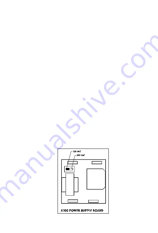
be selected as 120VAC or 240VAC by a selector switch on the
power supply board.
The supply voltage for which the relay is set will be clearly mark-
ed on the wiring diagram label attached to the outside of the
relay. If the supply voltage is to be changed, the cover must be
removed and the selector switch shown in fig. 2-6 set accordingly.
When changing the supply voltage be sure to mark the new
voltage on the terminal label for future reference.
Full accuracy of the Protect 4A relay will be maintained over a
wide range of supply voltages which are typically found in in-
dustrial environments (85-140VAC) or (170-275VAC) 48-62Hz.
When the control voltage drops below the minimum voltage,
the PROTECT 4A output contacts go into the trip condition to
provide fail-safe operation. Whenever control power is applied
to the Protect 4A, it will come on in the state present at loss of
power.
Since the reset for the Protect 4A relay is electrical, control power
must be applied when the relay reset button is pushed.
FIGURE 2-6 CONTROL VOLTAGE SELECTION
Summary of Contents for PROTECT 4A-120
Page 1: ...MOTOR PROTECTION RELAY INSTRUCTION MANUAL ...
Page 5: ...2 FIGURE1 1 PROTECT 4A TYPICAL SYSTEM CONNECTION ...
Page 11: ...8 FIGURE 2 2 PHASE CT DIMENSIONS FIGURE 2 3 GROUND FAULT CT DIMENSIONS ...
Page 21: ...18 FIGURE 3 1 FRONT PANEL LAYOUT ...
Page 35: ...32 FIGURE 4 1 SINGLE PHASE INJECTION TESTING FIGURE 4 2 100 AMP CURRENT SOURCE ...
Page 39: ...36 FIGURE 4 3 GROUND FAULT EARTH LEAKAGE TEST ...
Page 44: ...41 FIGURE 5 1 HARDWARE BLOCK DIAGRAM ...


