Instruction Manual, SMPTE HUT
INTRODUCTION
2
INTRODUCTION
The SMPTE HUT system enables you to replace long runs of the
bulky and expensive hybrid fiber cable that connects your camera
and CCU with inexpensive fibers alone. It does this by moving
the camera power injection from the CCU side to the cam side.
It consists of a breakout adapter, known as the HUT-CCU, that
attaches to the SMPTE connector on your CCU. This enables you
to connect 2 fibers going to the cam side using ST connectors,
and it also tricks the CCU into thinking that your camera is still
attached by the hybrid fiber cable.
At the cam side of these fibers is the CAM HUT, which takes these
2 fibers with ST connectors and routes them to a SMPTE hybrid
fiber connector. It also plugs into local mains power and injects
230 VAC for your camera into that same SMPTE connector which
now connects to the camera via a much shorter length of hybrid
fiber cable. The CAM HUT performs the same safety checks on
this cable as your CCU does, and it optionally allows remote
powering down of your camera from the CCU side as well as
optical repeating and remapping of the wavelengths to and from
the CCU.
FEATURES AND OPERATION
CAM HUT (cam side) unit
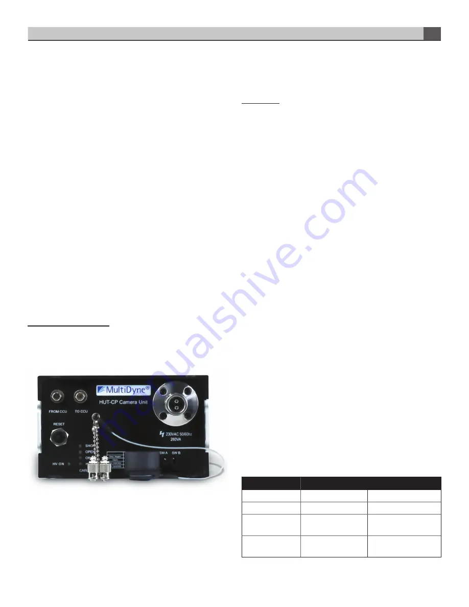
The CAM HUT basic version is shown in Fig. 1. There are 3
versions of the CAM HUT, described below.
There are 2 versions of the CAM HUT, and each has its own front
panel. These are shown in Fig. 2. The basic configuration, which
is the first panel, is to have the SMPTE hybrid fiber connector
to the camera and the 2 ST/UPC or duplex LC fiber connectors
populated on the front panel. These are labeled FROM CCU
and TO CCU. Optionally, the optical connectors can be located
on the rear panel instead, as shown in Fig. 3. In systems with
the optional optical repeater, it is important that the user be sure
that his up-link and down-link signals are matched to the proper
connectors consistently throughout the link.
Front Panel
RESET: This button resets a 2A thermal circuit breaker in series
with the SMPTE hybrid connector output. In the event of an
over-current fault that causes power to the cam to be removed,
as evidenced by the HV PRES LED being dark, and the button
popped out. Pressing this button restores power after the fault
is removed. Note that RESET does not restore functionality if a
SMPTE cable fault exists.
SMPTE CABLE Status LEDs:
SHORT: Glows red upon short or leakage of hybrid fiber cable
to ground. Upon power up, this LED may glow red for a few
seconds even if no short exists. This is normal.
OPEN: Glows red when cable is open or cam not connected. If
using a Hitachi camera, be sure to set the CAM TYPE switches to
the Hitachi positions, to bypass the OPEN cable test. Otherwise,
it will always fail. For Panasonic, Sony or Ikegami, set switches
for those cameras.
OK: Glows green indicating a properly connected hybrid fiber
cable.
HV ENAB: Glows green when the HUT attempts to apply 230VAC
to the hybrid fiber cable. This occurs only after all cable checks
have been completed successfully.
HV PRES: Glows green when 230VAC is actually present on
the hybrid cable. If HV ENAB is green but HV PRESS is off,
check to see if the circuit breaker has been tripped. If so, the
RESET button may need to be pressed after removing the fault.
Otherwise, there could be a failure of either the HUT relays or
power transformer, and the HUT will require service.
CAM HUT
CAM TYPE: Selects cameras according to table below:
Switch A (leftmost)
Switch B (rightmost)
Sony or Ikegami
down
down
Hitachi
down
up
Panasonic
3500 or 3800
up
down
Panasonic
3000 or 5000
up
up


