background image

Multicomp-pro


27 

Data Hold 

Data hold keeps the current reading on the display. 

(1) Press the Run/Stop panel key to stop the trigger, and the current reading is kept on 

the display screen. 

(2) Press the Run/Stop key again to continue triggering. 

Math 

The multimeter provides these math functions: Max/Min, dB/dBm and relative.


Only one 

operation can be enabled in the Max/Min, dB/dBm, or relative operation. 

Max/Min 

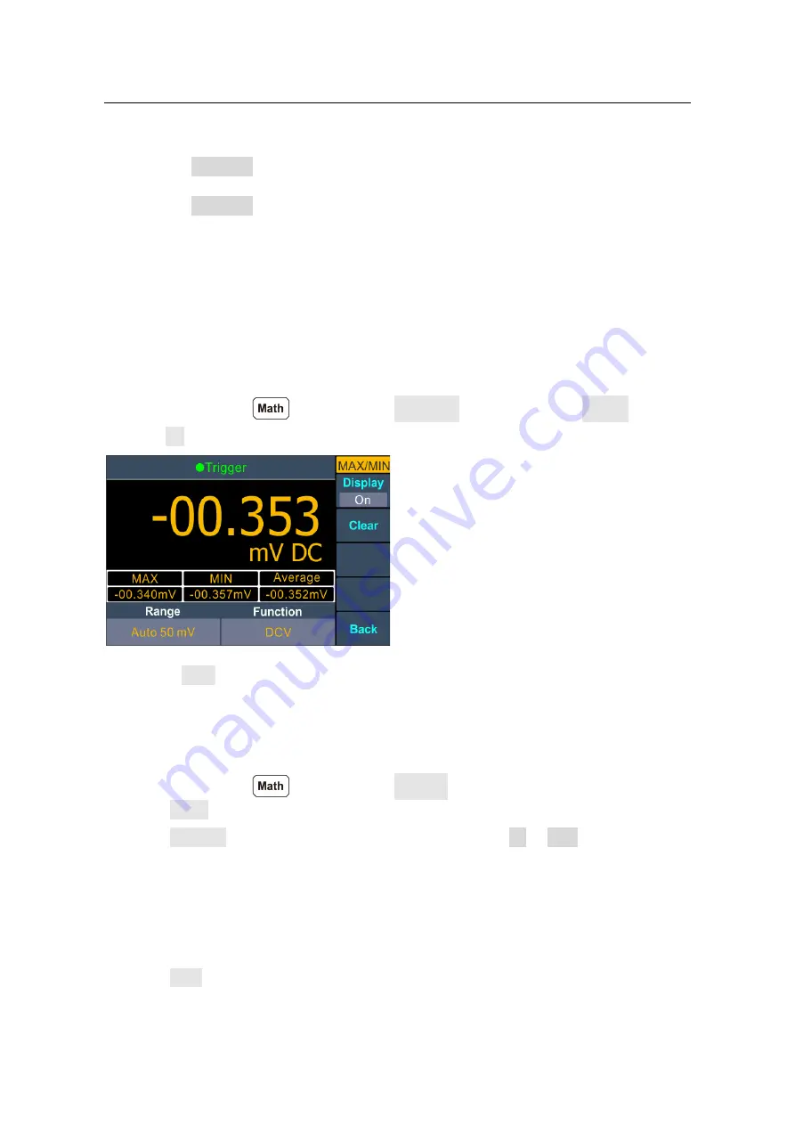
The Max/Min operation is used to calculate the max, min and average of the readings 

during the measurement period 
Press the front panel 

  key, press the MAX/MIN softkey, press the Display softkey 

to select On.


Remarks 


Press the Clear softkey to clear reading memory and restart statistics. 

dB/dBm 

The dB and dBm scaling functions only apply to ACV and DCV measurements. The 

functions allow you to scale measurements relative to a reference value. 
Press the front panel 

  key, press the dB/dBm softkey to access the menu. 

Press the Mode softkey to enable or disable the function. 
Press the Function softkey to select the operation function as dB or dBm.


dBm Function 

dBm function represents the absolute value of the power. The function calculates the 

power of the reference resistance according to the measured voltage, relative to 1 mW:   

dBm = 10 x log

10

 ( reading

2

 / reference resistance / 1 mW ) 

Press the Rel R softkey to select the reference resistance. The value may be 50 (default), 

75, 93, 110, 124, 125, 135, 150, 250, 300, 500, 600, 800, 900, 1000, 1200, or 8000 Ω.


Summary of Contents for MP730889

Page 1: ...i Digital Multimeter User Manual MP730889...

Page 2: ...ons 11 3 Functions and Operations 13 To Set the Range 13 Measurement Speed 14 Basic Measurement Functions 14 Measuring DC Voltage 14 Measuring AC Voltage 15 Measuring DC Current 16 Measuring AC Curren...

Page 3: ...33 Loading Errors DC Voltage 33 True RMS AC Measurements 34 5 Troubleshooting 35 6 Technical Specifications 36 7 Appendix 38 Appendix A Enclosure 38 Appendix B General Care and Cleaning 38 Appendix C...

Page 4: ...nstrument or other property might occur Safety Symbols Symbols on the Product The following symbol may appear on the product Direct current DC Warning risk of electric shock Alternating current AC Cau...

Page 5: ...roduct Refer to the user s manual for the Measurement Limits before connecting to the instrument Do not exceed any of the Measurement Limits defined in the following section Do not operate without cov...

Page 6: ...limit can also be expressed as 1000 Vpk maximum Current Input Terminal Measurement Limits The measurement limit from 10A input terminal to COM Input terminal is 10 A DC or AC The measurement limit fro...

Page 7: ...t CAT III applies to protect against transients in equipment in fixed equipment installations such as distribution panels feeders and short branch circuits and lighting systems in large buildings Meas...

Page 8: ...anual You can check whether there is any loss of accessories with reference to this description If it is found that there is any accessory lost or damaged please get in touch with our distributor resp...

Page 9: ...ticomp pro 6 Front Panel Overview Figure 2 1 Front panel overview Ite m Name Description 1 LCD Display the user interface 2 Menu selection Keys Activate the corresponding menu 86 5 mm 64 mm 2 4 5 1 7...

Page 10: ...ss or keys to increase or decrease the value 6 Operation Keys Run Stop Start or stop auto trigger When the trigger is stopped the displayed data will be held Record Access menus of manual record and a...

Page 11: ...Multicomp pro 8 Rear Panel Overview Figure 2 2 Rear panel overview...

Page 12: ...ndix C Line Fuse Replacement 3 AC Mains Input AC mains input connector User Interface Figure 2 3 User interface Single display Trigger Mode Reading Range Function Operation Menus Unit Status Icon Seco...

Page 13: ...l display Power On 1 Connect the instrument to the AC supply using the supplied power cord Warning To avoid electric shock the instrument must be grounded properly 2 Press down the power button at the...

Page 14: ...vice under test to the multimeter according to the method below To avoid instrument damage do not discretionarily switch the measurement function when measuring DC Voltage Measurement AC Voltage Measu...

Page 15: ...tance Measurement Continuity Test Diode Measurement Capacitance Measurement Frequency Period Measurement Temperature Measurement Resistance I Open or Closed Circuit I I Forward Bias Capacitance AC Sig...

Page 16: ...right menu you can press the key to switch between auto and manual range Press or keys to enable manual range and increase or decrease the measurement range 2nd Method Select the range in the measurem...

Page 17: ...voltage measurements Operating Steps 1 Enable the DCV measurement Press on the front panel to enter DCV measurement mode 2 Connect the test lead 3 Set the function Press the Function softkey to switch...

Page 18: ...measurements Operating Steps 1 Enable the ACV measurement Press on the front panel press it again to enter ACV measurement mode 2 Connect the test lead 3 Set the function Press the Function softkey t...

Page 19: ...the result See page 28 Relative Value Measuring DC Current This section describes how to configure DC current measurements Operating Steps 1 Enable the DCI measurement Press on the front panel to ente...

Page 20: ...measurement speed Press the Speed softkey to switch between Low Mid and High See page 14 Measurement Speed 6 Set the relative value Press the Rel softkey to turn on or off the relative operation For...

Page 21: ...uilt into the uAmA input terminal for overcurrent protection 10 over range for all ranges except 10 A range If the reading exceeds 10 5 A in 10 A range overload will be displayed 5 Set the measurement...

Page 22: ...omp pro 19 Measuring Resistance This section describes how to configure resistance measurements Operating Steps 1 Enable resistance measurement Press on the front panel to enter resistance measurement...

Page 23: ...peration For relative operation the multimeter subtracts the pre specified value of REL operation from the actual measurement result and displays the result See page 28 Relative Value Tip If the measu...

Page 24: ...s to increase or decrease the value The range for the 1 to 1000 The default is 50 5 Continuity measurements behave as follows Circuit resistance to be measured Display and beep Short circuit resistanc...

Page 25: ...behave as follows Forward pressure drop of diode Display and beep 0 to 3 V Displays measured voltage and the multimeter beeps when the voltage is below 0 7 V if beeper enabled 3 V Displays Open with n...

Page 26: ...the Rel softkey to turn on or off the relative operation For relative operation the multimeter subtracts the pre specified value of REL operation from the actual measurement result and displays the r...

Page 27: ...ts the pre specified value of REL operation from the actual measurement result and displays the result See page 28 Relative Value Measuring Temperature This section describes how to configure temperat...

Page 28: ...ue on the main display and the measurement value will be displayed 5 Set the temperature unit Press the Unit softkey to display temperature in degrees Celsius degrees Fahrenheit or K Kelvin The conver...

Page 29: ...nctions and their associated secondary measurements are gray back color indicates valid combinations Primary measurement function DCV DCI ACV ACI Freq Period RES CAP Secondary DCV DCI ACV ACI Freq Per...

Page 30: ...Press the Clear softkey to clear reading memory and restart statistics dB dBm The dB and dBm scaling functions only apply to ACV and DCV measurements The functions allow you to scale measurements rela...

Page 31: ...250 300 500 600 800 900 1000 1200 or 8000 Press the dB Rel softkey to select the relative value The relative value must be from 120 to 120 dBm default 0 Relative Value When the relative operation is t...

Page 32: ...ata table by serial number The icon will show up on the top of the display Note The measurement function can be switched during manual record Save only the main display readings 2 View the manual reco...

Page 33: ...ftkey to stop recording the data table shows the readings taken Press or keys to turn the page Note Automatic recording function supports switching measurement function In auto range the relay switch...

Page 34: ...d time The time always uses a 24 hour format 00 00 00 to 23 59 59 Press the Set softkey to edit the date and time Press the front panel key to move the cursor press or keys to increase or decrease the...

Page 35: ...from 2400 4800 9600 19200 38400 57600 or 115200 The default is 115200 Make sure that the baud rate matches that of the computer Press the Parity softkey select the parity from None Odd or Even The def...

Page 36: ...ance of the DUT Device Under Test is an appreciable percentage of the multimeter s input resistance as shown below Vs ideal DUT voltage Rs DUT source resistance Ri multimeter input resistance Error i...

Page 37: ...ut waveform are measured DC is rejected As seen in the figure above for sine waves triangle waves and square waves the AC coupled and AC DC values are equal because these waveforms do not contain a DC...

Page 38: ...l exists please contact us for our service 2 The reading does not change when a current signal is input 1 Check whether the test lead is correctly inserted into the current input terminals 2 Check whe...

Page 39: ...01 k 0 15 5 5 M 0 0001 M 0 3 5 50 M 0 001 M 1 10 Diode 3 0000 V 0 0001 V 1 10 Continuity 1000 0 1 Adjustable threshold Frequency 10 000 Hz 60 MHz 8 0 2 10 Capacitance 9 50 nF 500 uF 2 5 10 5 mF 50 mF...

Page 40: ...ency 10 MHz the specification is applicable to 3V AC input voltage 9 Specifications are for using the relative operation of math Using of non film capacitor may generate additional errors Specificatio...

Page 41: ...lectrical shock disconnect the instrument from AC mains power and disconnect all test leads before cleaning 2 Clean the outside of the instrument using a wet soft cloth not dripping water Do not make...

Page 42: ...ement leads and other cables from the instrument including the power cord 2 Use a flat blade screwdriver to remove the fuse box 3 Replace the fuse with a new one install it into the fuse box and push...

Reviews: