

Configuration of the terminal
System settings
6
30322507-02-EN
V7.20210115
21
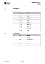
Function icon
Meaning
Calls up the screen for calibrating the speed sensor.
Calls up the screen with the counters.
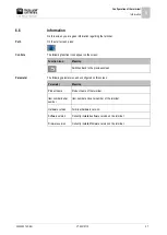
The following parameters can be configured on this screen:
Parameter
Meaning
Speed signal
Source for the speed signal.
Sensor - A speed sensor is connected to the terminal. The work screen
displays the icon:
.
CAN-Bus - The speed signal is received through the CAN bus.
Pulses per 100 m
Number of impulses sent by the speed sensor over a distance of 100m.
(Only appears when "Sensor" is selected as the speed signal.)
Work position signal Source for the work position signal.
Sensor - A work position sensor is connected to the terminal. The start
screen displays the icon:
/
CAN-Bus - A work position signal is received through the CAN bus.
No selection - A work position signal was not selected.
Working width in m
Current working width.
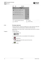
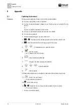
Calibrating the speed sensor
When calibrating the speed sensor, you determine the number of pulses sent by the sensor over a
distance of 100m.
If the number of pulses is known, the terminal can calculate the current speed and transmit it to the
connected job computer.
To calibrate the speed sensor:
The terminal is connected to the tractor signal socket.
In the "Speed signal" parameter, the "Sensor" value is selected.
1.
Measure and mark a distance of 100 m. The ground must correspond to the field conditions. The
distance should therefore lead over a meadow or a field.
2.
Position the vehicle with connected implement at the beginning of the marked distance.
3.
>
- Open the vehicle screen.
Parameter
Procedure