8 | 16
M0030.docx | Rev 1.8 | Modified on 14/06/2019 | © Remote Control Technologies Pty Ltd
Installation Guide
1
Install the control unit in a suitable location near the operator.
2
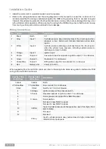
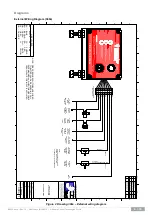
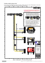
Refer to the wiring table below and the wiring diagram/s in this manual to connect the control unit. It is
recommended that the wiring is installed alongside the OEM wiring ensuring that it is secured at regular
intervals; this will provide protection from heat and abrasion, and any other excess damage that may occur
with extended vehicle operation. When securing the wiring to the OEM wiring, ensure that the loom is away
from moving vehicle parts which could lead to loom damage.
Wiring Connections
No.
Colour
Function
Description
1
Black
Earth
0 V
2
Grey
Input 1
Cylinder pressure okay (normally closed; the circuit opens when
pressure is low). Amber alert indicator illuminates when input
opens.
3
White
Input 2
Cylinder pressure discharge (normally closed; the circuit opens
when the cylinder loses pressure, indicating cylinder pressure
discharge) red alert indicator.
4
Orange
Input 3
Ignition input.
5
Purple
Output 2
Aux output (operates opposite to ignition output). 1 A continuous.
6
Green
Output 3
Fault alarm. 1 A continuous.
7
Yellow/Blue
Output 1
ETR ignition output for run solenoid. 5 A continuous.
8
Red
BVE
Power (8 to 35 V).
When upgrading from the old 7650 control unit, refer to the wiring table below as a guide to interface the 7650
wiring to the new 5884 control unit.
Part No. 7650
12-Pin Plug
Part No. 5884
8-Pin Plug
Description
1 Black
1 Black
Earth
2 Yellow/Blue
7 Yellow/Blue
Run solenoid, 5 A continuous.
3 Red
8 Red
Switch via 15 A circuit breaker.
4
4 Orange
Ignition supply via fire pressure switch.
5
5 Purple
Operates opposite to ignition output. 1 A continuous.
6
Sonar ground not supplied from 5884 fire panel.
7
6 Green
Sonar positive.
8
Not used in new 5884 fire panel.
9
Not used in new 5884 fire panel.
10
3 White
Input 2 cylinder pressure discharge (active open from high). Red
alert indicator.
11
Not used.
12
Not used.
2 Grey
Input 1 cylinder pressure okay (active closed to high). Amber alert
indicator when input opens.


