M0030.docx | Rev 1.8 | Modified on 14/06/2019 | © Remote Control Technologies Pty Ltd
11 | 16
Calibration
Calibration (CAL) Mode
1
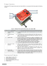
To enter CAL mode, press and hold the panel test button and apply power to the control unit. After six
seconds, all the alert indicators will flash.
2
Release the panel test button.
3
All alert indicators will be off, except for the one displaying the current shutdown delay period. The alert
indicators display the delay period as outlined below:
a)
Green – delay is 6 seconds
b)
Amber – delay is 15 seconds
c)
Red
– delay is 25 seconds
4
Activate and release the panel test button to change the periods required. Turn off the power to the control
unit when complete to save settings.
Note
The alarm will activate while in CAL mode and whenever the panel test button is pressed.
Special Note
1. When the 6-second delay to shut down is selected, the override operates for 20 seconds.
2. When the 15-second delay to shut down is selected, the override operates for 15 seconds.
3. When the 25-second delay to shut down is selected, the override operates for 10 seconds.
No Extension Mode
The 5884 can also be configured for no extension on shutdown. The process for setting this function is below.
1
Press and hold the control unit panel test push button once in calibration mode for more than 10 seconds
and then release it. You should now be in NO EXTEND mode (denoted by the flashing alert indicator):
a)
Green – Flashing: 6 s no extend
b)
Amber – Flashing: 15 s no extend
c)
Red
– Flashing: 20 s no extend
2
Activate and release the panel test button to change the periods required. Turn off the power to the control
unit when complete to save settings.
Note
Select the red flashing calibration setting, 20 s no extend
(Thiess specification).
Service Information
Service Schedule
The manufacturer recommends that the following service procedure should be performed at each machine’s
scheduled service interval.
Service Procedure
1.
Perform a visual inspection; include the following:
a)
Control unit
b)
Wiring connections and looms
c)
Fire suppression tank pressure switch (low)
d)
Fire suppression tank pressure switch (discharge)
2.
Perform a system test as per the following:
a)
Turn the ignition key to the on position and with the cylinder pressure correct, the alert indicator will
illuminate green. The output to the ETR circuit will be activated.
b)
Turn the ignition key to the off position and with the cylinder pressure correct, the green alert indicator
and ETR output will turn off. The auxiliary output will turn on.
c)
Push and hold the panel test button. The green alert indicator will turn off and the amber alert indicator
will turn on for two seconds. The red alert indicator will switch on after the preset period. The ETR


