7
Disassembly/Reassembly Instructions
HG-6 FLUSHING SYSTEM
TOOLS NEEDED: 3/8" Socket, 7/16" Wrench, Philips screwdriver, A103 Security screwdriver.
HG-6 DISASSEMBLY AND REASSEMBLY INSTRUCTIONS
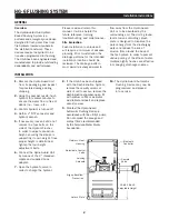
10.
Loosen clamping bolt on bottom
of outside face clamp.
11.
Slide clamp assembly away from
the unit’s 2" Flow Control Valve.
12.
Unscrew valve from 2" brass pipe.
13.
Remove six 3/8" bolts from
valve cover.
14.
Pull the top part of the
valve away.
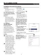
15.
Check valve for any damages
or debris in the inlet and outlet
holes on valve.
16.
Check diaphragm for any
damages and check for any
debris in the inlet and outlet
holes on inside of the valve
cover. When reinstalling valve
cover to base, all arrows must
point the same direction.
Reassembly
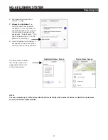
1.
Screw valve onto 2" brass pipe.
2.
Assemble sliding clamp assembly.
3.
Slide clamp assembly toward the
unit’s 2" Flow Control Valve.
4.
Assemble HG-6 housing by
installing the ten 1/4" bolts.
Don’t forget the corresponding
7/16" lock nuts inside the
housing.
Disassembly
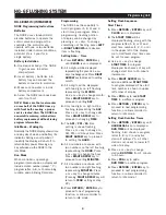
1.
If attached to a fire hydrant;
close hydrant’s water supply
and allow to drain.
2.
Relieve any remaining water
pressure within Hydro-Guard®
unit by opening sample port.
3.
Place HG-6 in area clear of
debris.
4.
Remove the six security screws
from top cover.
5.
Remove the four security
screws for the unit’s splash
pad assembly.
6.
Remove the ten 1/4" bolts
from the HG-6 housing.
It’s necessary to hold
corresponding 7/16" lock nuts
from inside the housing.
7.
Detach Latching Solenoid from
control valve.
8.
Detach electrical conectors
connecting the wiring of the
controller (NODE or T-2) and the
Latching Solenoid.
9.
Remove the four bolts from the
sliding clamp assembly prior to
removing the two inner clamps.
5.
Attach Controller to
Latching Solenoid.
6.
Install top cover with the six
security screws.
7.
Install the six security screws
from cover assembly.
8.
Reinstall diaphragm, following
inspection into valve’s top
section.
WARNING: Use caution to
avoid damaging plastic screen plug.
9.
Reinstall screws in valve and
tighten
WARNING: Use caution when
tightening screws. Overtightening
can damage valve body.
WARNING: Ensure flow arrows
on top and bottom of valve body
are facing the same direction and
match the flow pattern of the
flushing device.
!
!
!
BATTERY REPLACEMENT
HG-6 Built-In Node Controller
1.
Follow HG-6 Removable TBOS-II
Controller steps 1 – 3 (left) to
access on-board Programmer.
2.
Connect fresh industrial grade
9-volt alkaline battery and
reinsert it with harness into
Programmer (an optional
battery harness is provided
for redundancy and extended
battery life).
3.
Screw protective cap back
into place and hand tighten
securely.
1.
Screw protective cap back
into place and hand tighten
securely.
2.
Use Handheld Controller to
reset all programs and assure
flushing sequence is correct
prior to returning the HG-6 Unit
to service.
3.
Reinstall Exterior Housing Cover
and restore water supply to
unit.
4.
Confirm that desired flushing
sequences are correct prior
to returning the HG-6 Unit to
service.
5.
Reinstall Exterior Housing Cover
and restore water supply to unit.
Summary of Contents for Hydro-Guard HG-6
Page 11: ...11 Notes HG 6 FLUSHING SYSTEM...


