Mueller C1-36 Operating Instructions Manual Download Page 5

4

MUELLER

® 


C1-36 Drilling Machines

Operating Instructions

5

18. Unbolt adapter from valve and 

remove adapter and drilling machine 

from valve as a unit.
19. Advance boring bar by rotating 

feed crank counter-clockwise and 

remove hub retaining bolt, (retaining 

screw from cutter arbor or retaining 

screws from shank of solid drill.) 

Remove cut-out section of pipe, shell 

cutter, cutter hub or cutter arbor and 

pilot drill as a unit.
20. If cutting operation becomes 

difficult, follow one of these methods:
a) If cutter has difficulty in cutting, 

becomes dull or should stall 

after the cut is started, withdraw 

the cutter, close valve, remove 

machine and sharpen or replace 

cutter. Reassemble and proceed 

in the regular manner.

b) If cut is well along, release 

automatic feed and feed machine 

by hand by holding back on 

the feed crank at the rear of 

the machine a little each half 

revolution.

NOTE: Automatic feed should 

be used whenever possible. 

Automatic feed also provides 

the correct tool feed.

14. Continue the cutting operation 

until the cutter stops cutting or until 

feed indicator reads the amount 

shown in the travel chart. (See 

pages 7–10 for travel chart).
15. Check completion of cut by 

releasing automatic feed and 

attempting to advance cutter by 

rotating feed crank. If it does not 

advance easily, the cut is not 

completed and automatic feed 

knob must be pushed in to engage 

automatic feed for further cutting.
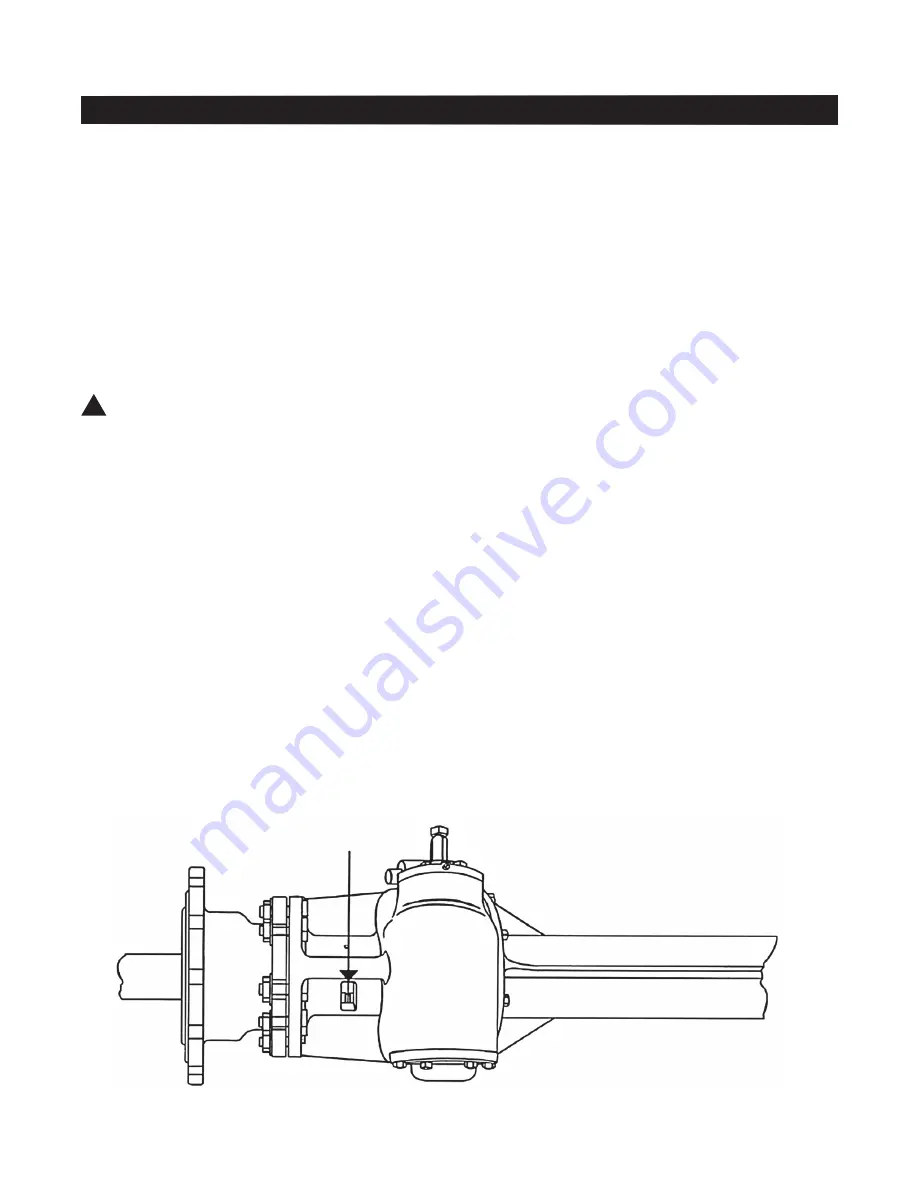
       CAUtIoN: stop advancing 

the boring bar when the limit line 

becomes visible through the drive 

box drain hole. see illustration at 

bottom of page 5.
Watch the travel carefully when 

making a 1

1

/

2

”/DN40 or 2”/DN50 

cut. Make sure that the front end 

of the boring bar, which is larger in 

diameter than the drill, does not hit 

the valve seat.
16. When cut is completed, release 

automatic feed and withdraw cutter 

to its rearmost position by rotating 

feed crank clockwise.
17. Close valve securely.

IMpoRtANt: stop advancing 

the boring bar if the limit line 

becomes visible through drive 

box drain hole. It will result in 

extensive damage to the machine. 

this applies to C1-36 machines 

manufactured prior to september 

1, 1995. C1-36 machines manu- 

factured after september 1, 

1995, or rebuilt after this date 

and that have “ot” or Model 6  

stamped on the  name plate have 

an overtravel protection feature 

which is designed to prevent 

damage should the boring bar 

be inadvertently advanced too 

far. Machines should never be 

allowed to overtravel. Feature 

does not prevent damage to the 

feed screw that could occur as 

a result of using dull drills or 

cutters.

!

Limit Line

Summary of Contents for C1-36

Page 1: ...perty damage 3 Safety goggles and other appropriate protective gear should be used Failure to do so could result in serious injury 4 Pressure test check for and repair leaks in all fittings and compon...

Page 2: ...ine Weight Length Chart description C1 36 Machine equipment 424 lb shipped in strong 221 kg wooden chest Machine Weight Only 270 lb 122 kg Machine Length 511 2 1308mm For complete information on the u...

Page 3: ...Packing Boring Bar Packing is the self adjusting type If packing leaks Replace it as follows 1 Remove hub retaining bolt Part No 545513 and nut Part No 61707 from boring bar 2 Remove 4 cap screws Part...

Page 4: ...on adapter flange and machine flange are flush 3 Release automatic feed by pulling out automatic feed knob or disengaging with Auto Feed Lever Directions are indicated on panel on rear of torque tube...

Page 5: ...by releasing automatic feed and attempting to advance cutter by rotating feed crank If it does not advance easily the cut is not completed and automatic feed knob must be pushed in to engage automatic...

Page 6: ...ut and replace the cotter pin 8 Resume normal operations Re engaging Overtravel Feature To re engage the boring bar after it has overtraveled while making a cut on a pipe that is under pressure 1 Turn...

Page 7: ...3 8 51 8 11 4 13 8 15 8 13 4 11 2 13 4 2 3 35 8 37 8 43 4 57 8 AGA Old Standard 11 4 11 2 17 8 21 8 2 31 8 11 4 11 2 13 4 17 8 11 2 21 8 3 45 8 11 4 11 2 13 4 13 4 11 2 17 8 21 2 33 8 41 2 51 4 11 4 1...

Page 8: ...5 8 37 8 41 4 13 8 11 2 13 4 13 4 11 2 13 4 21 2 27 8 33 8 35 8 33 4 45 8 51 8 65 8 13 8 15 8 13 4 11 2 17 8 13 4 2 23 4 31 8 31 4 3 33 4 4 41 2 11 4 13 8 15 8 15 8 11 2 15 8 2 23 4 31 4 31 2 33 4 51...

Page 9: ...7 8 41 8 43 8 21 8 21 4 13 4 21 8 21 2 3 31 4 33 8 3 33 4 37 8 41 4 13 4 21 4 21 2 31 8 33 8 33 8 3 35 8 33 4 4 13 4 13 4 11 2 13 4 2 25 8 23 4 3 21 2 31 4 33 8 33 4 11 2 13 4 2 21 2 23 4 27 8 23 4 31...

Page 10: ...1 4 21 2 3 31 8 31 8 23 4 31 4 31 4 33 8 13 4 23 8 21 2 31 8 31 4 33 8 23 4 31 2 35 8 33 4 21 2 25 8 23 4 33 8 31 2 35 8 3 33 4 33 4 33 4 11 2 13 4 2 25 8 23 4 27 8 21 2 3 3 31 8 11 2 17 8 2 25 8 23 4...

Page 11: ...hex bolts and discard C 6 Mount the base plate of the automatic feed lever to the mounting plate on the C1 36 machine using the 3 8 16UNC x 1 000 long bolts supplied in the kit These bolts screw Repl...

Page 12: ...r Co LLC its affiliates or other third parties Products marked with a section symbol are subject to patents or patent applications For details visit www mwppat com These products are intended for use...

Reviews: