


High Pressure Housing
Operation Manual
I
2
I
Safety Instructions
The sensor must only be used according to the Ex certificates listed
below
.
See product name plate for actual approvals.
To reduce risk of ignition in hazardous atmospheres, disconnect the
equipment from the supply circuit before opening. Keep assembley
tightly closed when in operation. For use according to UL-listing, con-
duit seals must be installed within 18" distance of the inclosure sensor
must be connected to a Class 2 power supply. The housing parts must
be kept as one unit.
They are not interchangeable with parts from similar housings. Only
tools applicable for use in explosive atmosphere must be used. When
mounting the rod in “ZONE 0” it is necessary to prevent any leakage
between “ZONE 0” and the surrounding environment. The sensor
house must be connected to an equipotential bonding system or an
earthing system.
PRECISION POSITION MEASUREMENT – HPH
This
H
igh
P
ressure
H
ousing (HPH) is ATEX/IECEx as well as UL and
cUL approved for use in hazardous locations with Temposonics
®
position sensors. The ATEX /IECEx, UL and cUL approvals cover flam-
mable gases, vapors, liquids and dust.
This housing is made to fit Temposonics
®
G-Series Start/Stop
Sensors and R-Series sensors with analog and digital outputs. Both
fixed cable and connector versions can be used. When using a standard
sensor in this housing you get a cost efficient solution for use in haz-
ardous locations which also allows easy sensor replacement. Several
design combinations are available to fit your application:
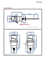
M18 or ¾"UNF mounting flange - M20 or ½" NPT cable gland thread -
top mounted or single/dual side-mounted. See combination chart. All
parts are made of 316L stainless steel. The housing is also available in
non-approved versions ensuring an outstanding protection to the sen-
sor when used in rigged applications with high humidity and agressive
gases.
TECHNICAL DATA
ATEX/IECEx
II 2G Ex db IIC T5 Gb
II 2D Ex tb IIIC T100°C Db
-40°C ≤ T
amb
≤ +75°C
ATEX Certificate: ExVeritas 16 ATEX 0192X
IECEx certificate: IECEx EXV 16.0014X
Compliance with
EN IEC 60079-0, EN IEC 60079-1
EN IEC 60079-26, EN IEC 60079-31
UL/cUL
Class 1, Division 1, Groups A, B, C, D
UL/cUL-Certificates:
USA: FTRV.E234045
Canada: FTRV7.E234045
In accordance with UL 1203 standard.
Material
Stainless steel AISI 316L (1.4404)
Cable Gland Threads
M20×1.5 (only with ATEX and IECEx approved cable glands (Ex db))
½" NPT (only with UL and cUL approved cable glands)
Ingress protection code
IP68 (only with professionally assembled and IP68 approved cable gland)
Approved sensors
G-Series Digital
R-Series Analog
R-Series Profibus
R-Series CANbus
R-Series SSI
Max. power consumption:
U = 24 VDC, I = 150 mA, P = 3.6 W
Mounting flange
M18×1.5 or ¾" - 16UNF - 3A
Pressure rating
350 bar
Peak Pressure
530 bar
Magnet type
Ring magnets
Level measurement
Float on request
Operating temperature
−40…+75 ºC
1
1/
T
amb
+ is limited to max T
amb
+ of used sensor −10 ºC