


Temposonics
®
E-Series CANopen
Operation Manual
14
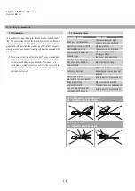
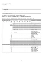
4.5 Magnet installation
Mounting the ring magnet
Install the magnet using non-magnetizable material for mounting
device, screws, spacers etc.
• Max. permissible surface pressure: 40 N/mm
2
• Max. fastening torque for M4 screws: 1 Nm; use washers,
if necessary
• Minimum distance between position magnet and any magnetic
material have to be 15 mm (0.6 in.).
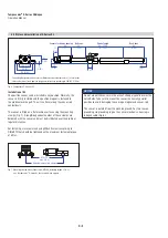
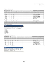
If no other option exists and magnetic material is used, observe the
specified dimensions (Fig. 11)
Fig. 11: Installation with magnetizable material
SW 46
Anziehmoment
≤ 50 Nm
> 30
Magnet
Empfohlene
Hydraulik-
abdichtung
Abb. 10
Einbau mit unmagnetischem Material
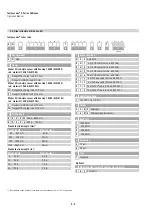
Magnet
nicht-magnetisbare
Distanzscheibe
> 15
min. 5
Abb. 11
Einbau mit magnetisierbarem Material
Abb. 12
Beispiel Sensorunterstützung
Alternative
Hydraulikdichtung
O-Ring 15,3 x 2,2
Sensor-Druckgehäuse
Stab mir Flansch
bleibt im Zylinder
Ringmagnet
Basissensor
Elektronikkopf mit Messeelement
austauschbar über zwei M4 Schrauben
mit 2,5 mm Innensechkant,
Anziehmoment max. 1,3 Nm
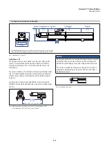
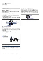
U-magnet
Sensor rod
Non-magnetic fixing clip (561 481)
3 ±1
(0.12 ±0.04)
M4
1
2
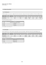
Fig. 12: Mounting device for U-magnet
Fig. 13: Example of sensor support
Mounting the U-magnet
Using a non-magnetizable mounting device is mandatory. The magnet
must not grind on the sensor rod. Alignment errors are compensated
via the air gap.
• Max. surface pressure: 40 N/mm
2
• Max. fastening torque for M4 screws: 1 Nm; use washer,
if necessary
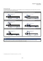
Large stroke lengths from 1 meter (39 in.)
Horizontally installed sensors should be supported mechanically
at the rod end. Longer rods require evenly distributed mechanical
support over the entire length. In this case (Fig. 13) the sensor rod
can be supported by fixing clips and an U-magnet can be used for
measurement.
NOTICE
A maximum permissible air gap of 3 mm (0.12 in.) must not be
exceeded.
Controlling design dimensions are in millimeters and measurements in ( ) are in inches
Null zone
≥ 5 (≥ 0.2)
Position
magnet
Non-magnetic
spacer
Magnetic
material
≥ 15 (≥ 0.6)
U-magnet
Non-magnetizable
entrainment device