


Page 506
Connect the vacuum line to the dis-
charge side of the pump, either in the
discharge opening or the drain tap. A
foot valve is not necessary when this
kind of device is used.
When a vacuum pump is not practical,
a foot valve in the suction inlet can be
used to prevent liquid from running out.
The pump and suction line can then be
filled completely from an outside source.
A vent opening will be necessary during
filling to let air escape. A tight foot valve
will keep the pump constantly primed so
that automatic operation is possible. The
valve should be inspected regularly to
see that it does not develop leaks which
would allow the pump to run dry.
Optional self-priming casings are avail-
able for MTH pumps allowing priming
when a vacuum pump or foot valve is
not practical. Refer to specific literature
for details.
There are four components to the self
primer:
1. A check valve - necessary to main-
tain a vacuum in the suction line as
surging occurs in the pump.
2. An air eliminator - used on the dis-
charge side of the pump to separate
air from liquid so the liquid can be
used again as air is carried through
the pump.
3. A recirculating line - carries liquid
from the air eliminator to the suction.
4. A fluid chamber - used on the inlet
side to provide a supply of fluid to
speed up priming.
Small suction lines are desirable to
minimize priming time.
Using the self priming casing, it is only
necessary to:
1. Open the plugs in both the inlet and
discharge chambers.
2. Pour fluid in one until both are full.
3. Tighten both plugs.
4. Turn on the pump.
Priming time depends on lift, volume of
air in the suction line, and the size of
the regenerative turbine pump used. If
priming time is long and the pump be-
comes warm, refill the priming chambers
with fresh liquid. Most turbine pumps will
pump twenty-six to twenty-eight inches
of mercury vacuum with cold water in
the pump, but have very little capacity
and therefore are not practical at lifts
over twenty-two feet.
The best way to prime a pump and keep
it primed is to use a flooded suction.
While this is not always practical, it does
provide a number of advantages. The
likelihood of pump damage from dry run-
ning is eliminated. Suction lines may be
large, reducing line losses and minimiz-
ing the potential of cavitation damage.
There are no check valves or priming
devices to fail or require maintenance.
Whenever possible, design pumping
systems with flooded suction.
3H Starting
Before starting a pump for the first time,
be sure that all the preceding operations
have been carried out. Proper rotation,
priming, and a free turning pump are
most important.
1. Start the pump with the minimum
possible line restriction.
2. Open discharge valves before press-
ing the starter.
3. Start the pump and let the system
clear of air.
4. Listen for foreign material being car-
ried through the pump.
5. Slowly close necessary valves or oth-
erwise place the pump into service.
6. Listen for indications of undue load or
other sounds indicating problems.
7. Use a clip-on ammeter to check for
a steady load after approximately
fifteen minutes of operation.
3I Stopping
It is best to stop the pump with the
least discharge head possible both for
minimizing strain on components and to
be in low power mode in anticipation of
T31 SERIES
4.
Maintenance
CLOSE COUPLED PUMPS
A.
Seals
B.
Cooling Water
C.
Lubrication
4A Seals
Mechanical seals are used in MTH
Pumps to eliminate the maintenance
that is normally associated with packing
boxes. This does not, however, mean
they can totally be ignored. Check a new
installation for seal leakage.
Maintenance of seals consists primarily
of periodic observation, looking for the
first signs of failure. An occasional drip
that continues to worsen is an indica-
tion that the seal has failed and must be
replaced. Follow the appropriate disas-
sembly/assembly instructions. Always
shut down a pump with failed seals
as soon as possible. Leaky seals are
usually followed by bearing failures and
then possible pump damage as rotating
parts become mis-aligned.
4B Cooling Water
If a heat exchanger is used to supply
cooling water for the seals, check the
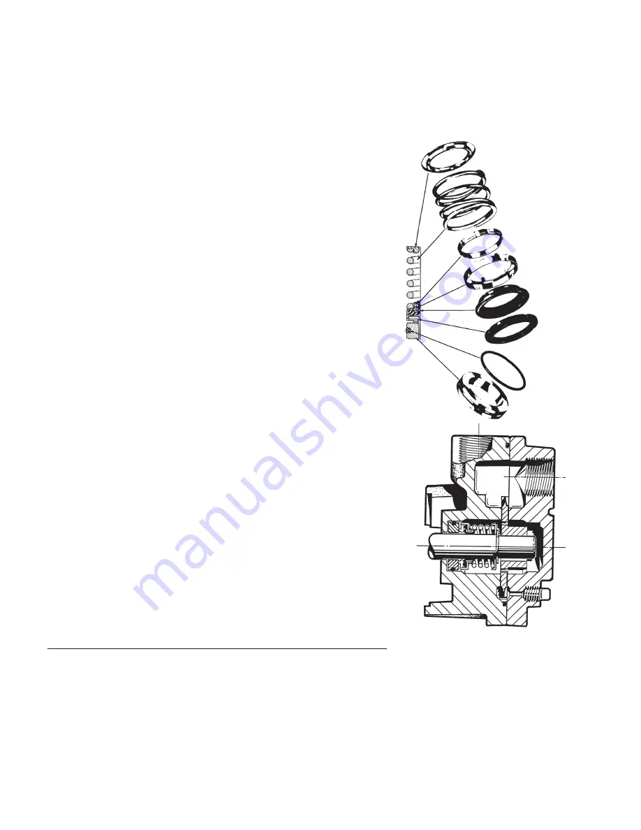
Figure 4-2 Standard Seal Consrtuction
Figure 4-1
Seat
"O" Ring
Washer
Fexible
Diaphragm
Retainer
Drive Ring
Spring
Spring
Holder
restarting. If the pump will be down for
more than a few weeks it is advisable to
drain it. Follow the instructions for long
term storage, Section 1, 1B Storage.
After any prolonged stoppage, turn the
pump over by hand before restarting, to
be sure it is free.


