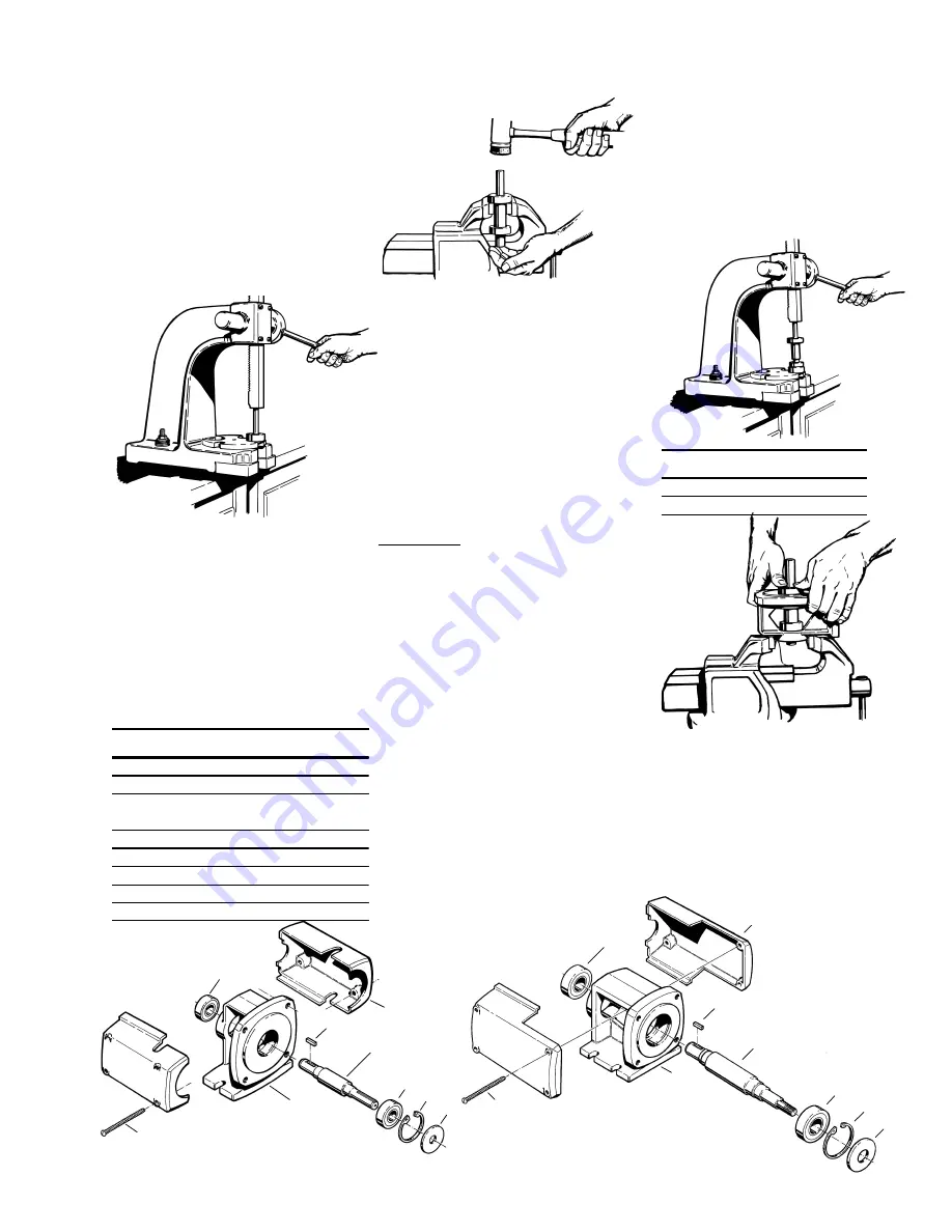
Page 513
5. Using a plastic or wooden mallet,
gently tap on the end of the shaft
until it slides out of the frame. Both
bearings should come out with the
shaft. Do not use a metal hammer,
severe damage to the shaft will
occur.
6. Using the arbor press, remove the
two (2) bearings from the shaft.
Refer to Figure 4-21. If the inner
race is well supported during this
operation, no damage will be done
to the bearings.
bearing is removed. Refer to Figure 4-
22.
and outside diameter, refer to Chart
1, should be used between the arbor
face plate and the lower bearing to
insure proper installation, and to
prevent bearing damage. The
bearings must seat against the
shoulder for proper alignment. Refer
to Figure 4-23.
*Also refer to Alternate bearing
installation procedures.
30
23
17
24
4
21
3
33
24A
Figure 4-19 P3 Bearing Pedestal
4
P3 & P15 BEARING PEDESTAL
NAME/DESCRIPTION
PART NO. QTY.
Bearing Pedestal
3
1
Snap Ring/Bearing Retainer
4
1
Shaft
17
1
Flinger
21
1
Key Coupling
23
1
Ball Bearing/Inboard
24
1
Ball Bearing/Outboard
24A
1
Coupling Guard/Halves
30
2
Capscrew
33
4
Figure 4-21
If an arbor press is not available, a
bench vise may be substituted using
the following procedure.
1. Remove the pedestal and close the
jaws to approximately 1-1/8" for
model P3 and 1-3/8" for model P15.
2. Place the shaft with either bearing
resting on top of the jaws and gently
tap on the end of the shaft until the
Figure 4-22
3. Repeat step 2 to remove the other
bearing. Good support used on the
inner races will prevent bearing
damage.
4C Inspection of Components
Thoroughly clean all parts. All compo-
nents should be examined for wear and
corrosion. Replace any parts showing
visible wear.
Check to be certain that a press fit still
exists between the shaft and the bearings.
New bearings, or at least cleaned and
regreased bearings, are recommended.
Check the shaft for galling, pitting, and
corrosion. Surface corrosion on the pump
portion of the shaft must be removed so
the seals will slide freely during assembly.
The shaft diameter should be no smaller
than .002" below the nominal fractional
seal sizes. Remove any nicks or burrs
which may have occurred during disas-
sembly. Reclean parts as necessary.
4D Reassembly
All parts should be visually inspected and
cleaned or replaced as outlined in 4C
above. It is recommended that the
bearings be replaced any time the bearing
pedestal is disassembled for service.
1. Using an arbor press, install the
bearings on the shaft prior to installing
the shaft into the pedestal. A steel
“donut” with the proper inside diameter
P3
P30
Inside Diameter
1"
Outside Diameter
2"
Figure 4-23
CHART 1
Figure 4-24
30
23
17
24
33
24A
3
Figure 4-20 P15 Bearing Pedestal
2. Place the pedestal, pump mounting
surface up, in a vise or suitable
fixture and insert the bearing
assembly. It should be possible to
install the shaft assembly with firm
thumb pressure. Refer to Figure 4-
24. If more force is required, the
butt end of a hammer handle or
plastic mallet may be helpful. The
shaft assembly should never be
forced or driven in.


