


UNIT INSPECTION
Inspect the unit for damage. Report
any damage to freight carrier im-
mediately. Check motor nameplate to
make sure voltage and phase match
the available power supply.
INSTALLATION
Locate the pump as close to the
liquid source as possible. Protect
the pump from freezing. The pump
should be located at a low point to
keep the impeller submerged at all
times. Always leave room around the
pump for servicing and ventilation.
Units may be installed horizon-
tally, inclined, or vertically. All piping
should be independently supported
and never forced into fi tting, this will
cause undue stress and could cause
binding within the pump.
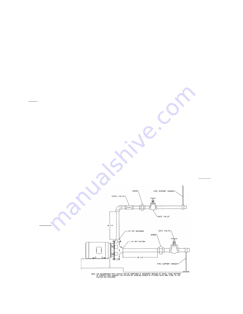
SUCTION PIPING
Always use pipe that is the same size
or one size larger than the suction
size of the pump. NEVER use pipe
smaller than the pump suction size.
The D91EF has a 2” NPT suction and
we recommend a section of pipe 20
inches long as the lead suction pipe.
See Typical Piping Diagram fi gure
1-1. This allows for a smooth even
entry of liquid into the impeller. We
also suggest installing a gate valve
and a union so the pump can easily
be isolated for servicing.
CAUTION -Never use the suction iso-
lation valve to throttle the pump.
Make sure all joints are tight. Avoid
air pockets. If an eccentric pipe
reducer is used, make sure it is
installed straight side up. Air in the
suction line can cause the pump to
cavitate. Always make sure suction
pipe and fi ttings are independently
supported. NEVER use the pump to
act as pipe support, this could make
the pump bind or break.
DISCHARGE PIPING
Always use pipe that is the same
size or one size larger than the
discharge size of the pump. If you
use pipe smaller than the 1 1/2”
NPT discharge on the D91EF, the
pumping capacity will be diminished.
We recommend a section of pipe 15
inches long as the lead pipe out of
the pump discharge. A check valve,
gate valve and a union should also
be installed in the discharge line for
pump throttling and servicing. See
Typical Piping Diagram fi gure 1-1.
Make sure the discharge line is well
supported. NEVER use the pump as
pipe support.
ELECTRICAL CONSIDERATIONS
Electrical supply must be a separate
branch circuit with fuses or circuit
breakers. Install a disconnect switch
as close to the pump as possible.
Wire in accordance with the National
Electric Code and local codes where
applicable.
CAUTION -Always disconnect electri-
cal power when handling the pump or
controls.
Motors must be wired for proper
voltage. Motor wiring diagram is on
the motor nameplate. Single-phase
motors are usually furnished as dual
voltage 115/230/1/60. Three phase
motors are usually furnished as tri
voltage 208/230/460/3/60. All three
phase motors require a magnetic
motor starter and thermal overload
protection. Single-phase motors up
to and including 1 horsepower have
built in thermal protection. Check
motor nameplate to confi rm overload
protection is built in. All single-phase
motors above 1 HP require magnetic
starters and thermal overload protec-
tors. Always limit your wire size so
the maximum voltage is no more than
10% of motor nameplate voltage at
the motor leads. If this voltage drop
is exceeded, motor and pump life will
be greatly diminished.
MOTOR ROTATION
The correct motor rotation (when
viewed from the motor end of the
pump) is clockwise. Pop cap off the
back of the motor; the motor shaft is
now exposed for viewing. Switch the
power on and off quickly and observe
the motor shaft. If the rotation is
counterclockwise change any two
motor leads on a three-phase motor.
Single-phase motors are nonrevers-
ible.
PUMP STARTUP
Make sure the suction gate valve
is wide open; when the pump is in
operation this valve should never be
throttled. Open the discharge gate
valve about 1/4 open. This will prime
the pump and force air out. NEVER
Figure 1-1